The sixteen year four month career of D5008/24008 saw allocations to London Midland Region, Southern Region & Scottish Region depots.
Built Derby Locomotive Works.
Full size fuel & water tanks (retained until withdrawn).
Four upper and four lower air filters on non-BIS side, three upper and four lower on BIS side (standard arrangement).
Time between last Classified repair and withdrawal: ?? months.
Time between withdrawal & scrapping: 9 months.
Allocations
The frames for D5008 were laid down at Derby Works during December 1958 and was delivered new to Crewe South (5B) on February 28th 1959, but then immediately loaned to Derby (17A). Further transfers were:
March 16th 1959 to Hither Green (73C) on loan.
May 1959 to Crewe South (5B).
May 1959 to Toton (18A) on loan (for test purposes).
September 1959 to Derby (17A).
October 1959 to Crewe South (5B).
October 1959 to Camden (1B).
January 1960 to Hither Green (73C) on loan.
July 1962 to Camden (1B).
September 1962 to Watford (1C).
October 1962 to Carlisle Upperby (12B).
December 1962 to Camden (1B).
January 1963 to Crewe North (5A).
September 1965 to Willesden (1A).
January 1966 to Rugby (1F).
January 1965 to Camden (1B).
April 1966 to London Division (D01).
April 1967 to Stoke Division (D05).
March 1971 to Eastfield (65A) on loan, made permanent April 1971.
July 7th 1975 to unserviceable store.
August 16th 1975 withdrawn.
Renumbered July 1974.
24008 was stored at Cadder Yard from July 1975 to October 1975, then at Glasgow Works until February 18th 1976 when it was forwarded to Doncaster Work, being scrapped during May 1976.
Works Visits
Works visits (records incomplete).
Noted Eastleigh Works July - August 1961.
Noted Derby Works January, February, June, July & August 1963.
Noted Derby Works May - July 1964.
Noted Derby Works August 1965.
Noted Derby Works May & October 1966.
Noted Crewe Works May 1968.
Noted Glasgow Works October 1971.
Noted Glasgow Works March - October 1974 (fire damage - continuous?).
Highlights
1959
The frames for D5008 were laid down in the last quarter of 1958 with the locomotive entering traffic at the end of February. Although initially allocated to Crewe (5B) D5008 was immediately transferred to Derby and then almost as swiftly transferred to Hither Green (73C), part of a loan of fifteen Class 24s from the LMR to the Southern Region.
D5007 & D5008 were noted at Hither Green on March 16th.
At the end of April D5008 returned to Derby for a series of tests, being re-allocated to Toton (18A) for this purpose, D5017 replaced it on the Southern Region.
This series of controlled mobile tests were conducted on a selection of the newly built diesel locomotive types to detail their performance and efficiency characteristics, these were conducted over a variety of speeds and power applications using the LMR Mobile Test Plant. The tests were to include a BR/Sulzer Type 2 with D5008 being chosen to participate. It had already completed 2,624 miles in service and would cover a further 4,211 miles during the tests.
The tests were undertaken during May & June by the Locomotive Testing Section, CM&EE Dept, LMR on behalf of the Locomotive Testing Joint Sub-Committee. To ensure the locomotive was a fair representative of its build it was subjected to static load tests on the Derby Locomotive Works test plant prior to the road testing. These initial tests revealed at the full controller setting the load regulated portion of the engine-generator characteristic was higher than the designed curve, attributable to the auxiliary power demand being lower than designed and that the engine output was high. No adjustment was made since the engine output was within prescribed tolerances. It was noted that due to the type of governor fitted there was a considerable rise in engine speed as unloading took place.
Several days of road testing were carried out to determine the current-speed relationship of the traction motors in all fields, which would reveal if the values of the field divert resistances were correct. It was noted that variations in generator field temperature caused field diversion and unloading to occur at widely varying speeds, indicating that the values of the field divert resistance was somewhat excessive. This was brought to the attention of the manufacturers, no changes were made at this time due to certain practical difficulties.
Following these preliminary tests a series of constant speed 'performance' tests were carried out on the Toton - Leicester - Rugby - Market Harborough - Derby - Toton route. Tests were carried out at seven different settings of the driver's controller, corresponding to nominal engine speeds of 330, 400, 450, 500, 550, 650 & 750rpm. The lowest speed of 330rpm is indicated by 'notch 1' on the controller, at this setting the diesel engine is unloaded throughout the range of road speed. Apart from notch 1 the power handle gives a stepless control of the power output, therefore the engine speed is infinitely variable between 330 & 750rpm. Where possible one of the above controller settings was employed throughout the whole of a particular test run. Each run was divided into ten or more sections of constant road speed, varying between five and ten minutes duration. Speeds were selected to cover the range at each controller setting in increments of 5mph. Over the lower speed range increments were increased by 2.5mph. Thus each test was carried out at constant road speed, controlled by the Mobile Test Units and at constant engine speed, imposed by the fixed controller setting.
The Amsler recording table in the dynamometer car kept continuous records of a number of functions including road speed, drawbar tractive effort and fuel consumption. Meters installed on the instrument desk in the dynamometer car recorded at one minute intervals the following:
main generator current & voltage
main generator field current & field voltage
main generator interpole voltage drop
auxiliary generator voltage
exciter seperate field current & voltage
traction motor current
traction motor interpole voltage drop
traction motor field voltage drop
diesel engine RPM
Because the auxiliary generator output was subject to variable demands from the two-speed radiator fan and intermittent operation of the compressor, its output was continuously recorded at the instrument desk.
Readings on the locomotive itself covered systematic pressure & temperature readings of the fuel oil, lubricating oil, boost air, cooling water and engine exhaust circuits. A number of tests were also carried out with two of the traction motors isolated and the diesel engine running at full speed.
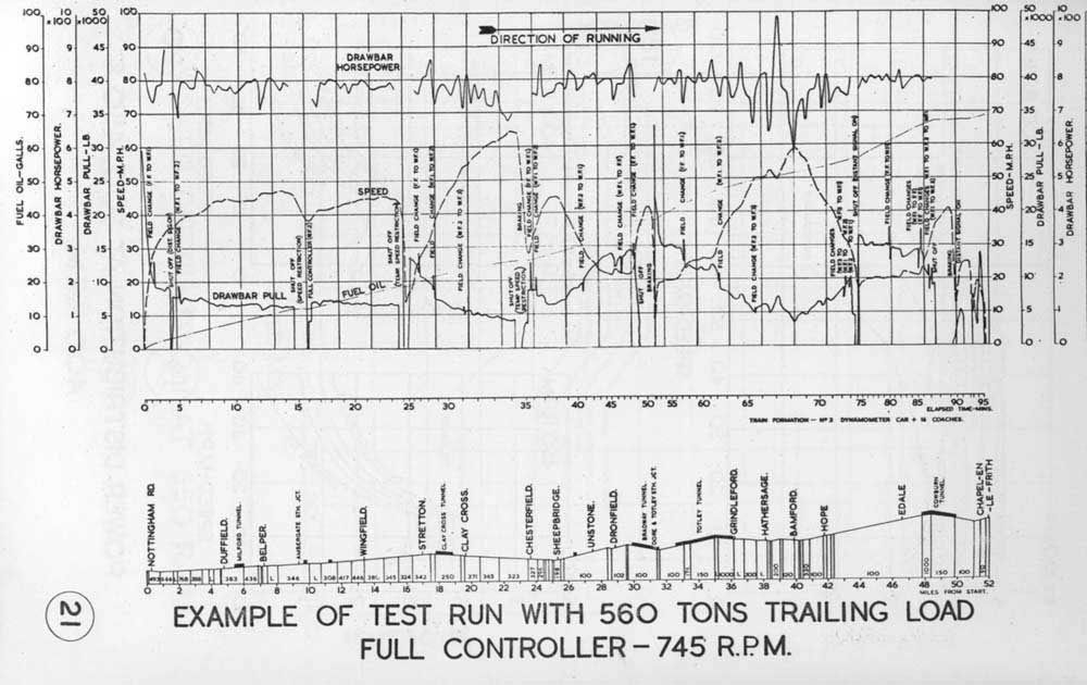
Following completion of the constant speed tests a variable speed run was completed to demonstrate the practical application of the test results in normal service. This was made with coaching stock and dynamometer car totalling 560 tons. This load was chosen to give low balancing speeds on the steepest sections of the test route when working at full power. It would also demonstrate the capabilities of the locomotive in hauling a heavier passenger train than would normally be expected in regular service. The test was carried out over the Toton - Derby - Chesterfield - Edale - Chapel-en-le-Frith - Peak Forest - Ambergate - Butterley - Toton route. The performance information obtained from the constant speed tests was used to establish the timings for this run. The timings were based on full power output with the locomotive worked at full controller throughout, barring signal checks and permanent way slacks. Actual point to point timings were in close agreement with the calculated times.
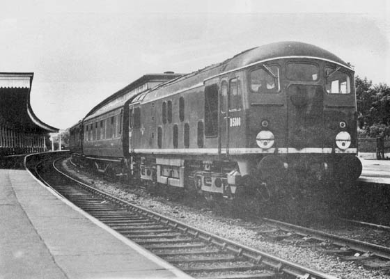
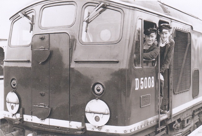
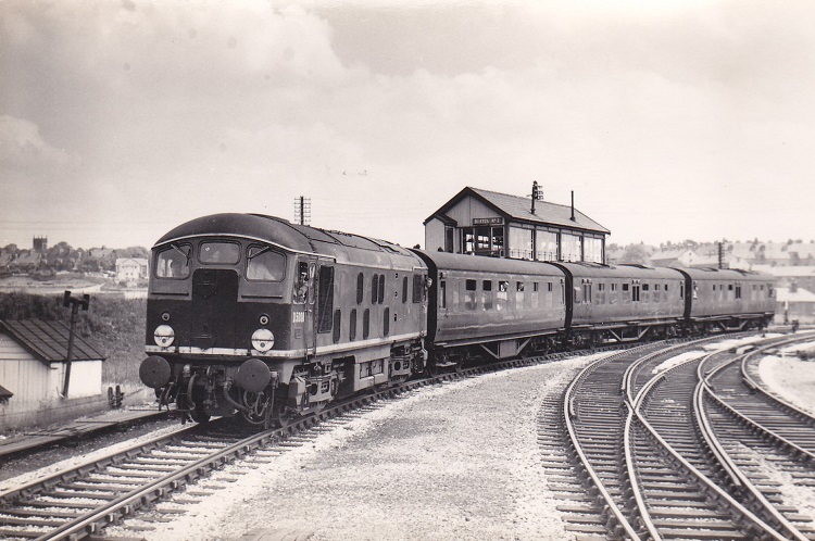
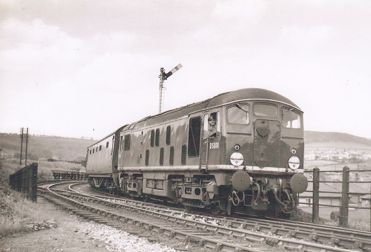
Two views of D5008 at Market Harborough, the top view is borrowed from the BTC report (photographer W H King), whilst the lower view shows driver Bramwell & fireman Dove (courtesy Geoff Dove).
The tests with D5008 were carried out entirely according to plan, defects were only of a trivial nature and did not impact the operation of the locomotive. After the tests were completed D5008 was re-allocated back to Derby (17A) in October, then quickly on to Camden (1B) in November, with D5008 noted at Willesden on November 4th.
One interesting job for D5008, believed to be in 1959 was the working of a 'mobile test unit' over the Uttoxeter - Rocester - Buxton line, the section north of Rocester had closed to passenger traffic during November 1954. There cannot be too many Class 24's that worked over this picturesque route.
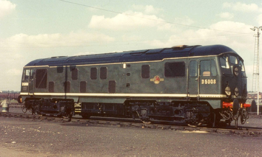
Condition September: green livery with frame level stripe, full size fuel & water tanks, no blanking plates, hand/footholds present, cantrail water filler cover present, ridge sided sandboxes, two-rung bogie mounted footsteps, four upper/four lower ventilators on non-BIS side, three upper/four lower ventilators on BIS side.
The winter timetable commencing November 2nd found D5015/16/18/19 taking over some of the local workings out of Euston. D5017 was still on loan to the SR having covered for D5008 which had been at Toton earlier in the year for tests, though by November 4th D5008 had reached Willesden for empty coaching stock duties, working alongside Type 1s D8035 - D8038.
1960
D5008's stay at Camden was brief, it moved back to Hither Green (73C) in January.
1961
D5008 & D6539 worked the 11.10 Charing Cross - Dover on March 4th.
On August 9th Eastleigh Works hosted its annual Open Day, modern traction represented by D3667 & E5008 whilst D5008 & D5009 were under repair in the main workshops, D5008 had arrived at the Workshops during July.
Condition August: green livery with frame level stripe, full size fuel & water tanks, no blanking plates, hand/footholds present, three upper/four lower ventilators on BIS side, no additional Southern Region disc brackets on No.1 cab.
1962
During 1962 the loaned Type 2s were able to return to the LMR D5008 to Camden (1B) in August. Despite its time on the Southern Region D5008 was never fitted with the additional brackets for disc or headboard use.
During November D5008 was briefly allocated to Carlisle (12B) before returing to Camden in December.
1963
D5008 continued its wanderings, moving to Crewe (5A) in January before returning south to Willesden (1A) in September.
Condition date uncertain (but after outshopping from Derby): green livery with small yellow warning panels, curved upper corners, full size fuel & water tanks, no blanking plates, hand/footholds present, ridge sided sandboxes, two-rung bogie mounted footsteps, engine exhaust located above engine room, four upper/four lower ventilators on non-BIS side
1965
After some five years as a diesel multiple unit working the 07.34 Lichfield - Birmingham and 17.45 return reverted to diesel haulage! On the first day of this diagram, January 26, D5008 worked both trips.
D5008 was on empty coaching stock duty at Euston on the morning of November 18th.
1966
D5008 moved to Rugby (1F) in January.
During 1966 D5008 was noted at Derby Works during May & October. Possibly it had been called to Derby due to receiving minor collision damage to the No.1 end, specifically the driver's side sandbox and bogie mounted footsteps were heavily damaged, the cab handrails are missing and there appears to be a scrape on the cab sheeting.
Condition date uncertain but 1966: green livery with small yellow warning panels, curved upper corners, full size fuel & water tanks, no blanking plates, hand/footholds present, ridge sided sandboxes, two-rung bogie mounted footsteps, engine exhaust located above engine room, three upper/four lower ventilators on BIS side.
1967
On March 24th D5008 was noted with a demolition train at Great Houghton on the Northampton - Bedford line.
With the electrification virtually complete at the southern end of the WCML the duties of the Class 24s were increasingly replaced by the AM10s on the suburban passenger duties and the newly arriving Class 25s on the local freight and parcels workings. Thus all the Class 24s were eventually moved to the Stoke Division (D05) with D5008 moving northward in April.
On July 1st D5008 was noted at Stockport with a Llandudno - Newcastle service, with Black Five No.45027 taking over the passenger train for the next part of the journey.
On the afternoon of September 30th D5008 & D5019 were northbound at Acton Grange with a freight, the locomotives later returned southbound light engines.
On the afternoon of November 26th D5008, D5077 & D5092 were stabled at Crewe.
1968
On the afternoon of December 7th 5008 was noted at Alsager with a down freight.
1969
With a downturn in traffic and a surplus of Type 2s the LMR stored or withdrew a number of the first twenty Class 24s. However 5008 remained in service during this purge.
On the early afternoon of May 4th 5008 was at Crewe with a permanent way train.
On the afternoon of June 4th 5008, 292 & 1521 were light engines at Crewe.
On the afternoon of September 17th 5008 was noted at Crewe north holding sidings, keeping company with 26016.
1971
In March as part of a large set of re-allocations 5008 moved to Eastfield (65A) being part of the scheme to allow the Scottish Region to withdrawn its few remaining Clayton & North British built locomotives. This was the last transfer for 5008.
Condition March (??): blue/yellow livery, gangway doors sheeted over, headcode discs centered on cabfront, full size fuel & water tanks, circular gauge fitted to fuel tank, no blanking plates, hand/footsteps plated over, ridge sided sandboxes, three-rung bogie mounted footsteps, bodyside valencing removed.
1973
Wednesday, May 17th proved to be quite a day for mishaps on the Scottish Region.
The day began with 5308 derailed at Burnhouse Weighs and 3384 going through the stop blocks at Mossend Yard. As 5008 was leaving Cadder Yard it came into a sidelong collision with 5375 running light. Five wagons hauled by 5008 were derailed, two containing scrap iron cascaded around the Class 27.
During the afternoon of May 27th 5008 was noted passing Haymarket with a ballast train.
1974
Condition April: blue/yellow livery, gangway doors sheeted over, headcode discs centered on cabfront (no SR headboard/disc brackets on either cab), full size fuel & water tanks, circular gauge fitted to fuel tank, blanking plates fitted, hand/footholds plated over, ridge sided sandboxes, three-rung bogie mounted footsteps, body side ventilators 4/4 non-BIS side & 3/4 BIS side.
1975 - 1976
The summer of 1975 brought major reductions in the fleet of the operational Class 24s with the Scottish Region taking many out of service including 24008, being stored in July and withdrawn during August.
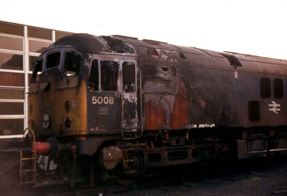
The specific cause for the withdrawal of 24008 are not known to the writer but it had spent considerable time in Glasgow Works between March & October 1974 under repair following serious fire damage in the vicinity of the No.1 cab. Yet nine months later the locomotive was permanently withdrawn from service, despite that recent extensive repair.
On February 18th 24008/95/98 1976 were moved from Glasgow Works to Doncaster Works for scrapping, by May 1976 24008 was no more.
Condition final: blue/yellow livery, gangway doors sheeted over, headcode discs centered on cabfront (no SR headboard/disc brackets on either cab), full size fuel & water tanks, circular gauge fitted to fuel tank, blanking plates fitted, hand/footholds plated over, straight sided sandboxes, three-rung bogie mounted footsteps, body side ventilators 4/4 non-BIS side & 3/4 BIS side.
![]()
Data from the BTC Testing report.
The following information comes from the testing report relating to the design data & prinicipal dimensions, evolution of the design means that certain of the data will be applicable to all 151 Class 24's whilst other details will refer only to the first twenty:
Locomotive
Wheel Arrangement: Bo Bo
Length Overall: 50ft 6in
Weight in working order: 79tons 16cwt
Maximum rail tractive effort: 40,000lb
Continuous rail tractive effort: 21,300lb at 14.8mph
Maximum speed: 75mph
Maximum axle load: 19tons 19cwt
Minimum curve negotiable: 4.5chains
Fuel tank capacity: 630 gallons
Brakes: Air on locomotive, vacuum on train
Wheel diameter: 45in
Diesel Engine
Maker: Sulzer
Type: 6LDA28
Rated output: 1,160hp at 750rpm
BMEP at rated output: 151 lb/sq in
Designed fuel consumption: 0.371 lb/bhp hour
Cycle: four stroke
Cylinders (number/bore/stroke): 6/280mm/360mm (11.02in/14.17in)
Combustion chamber: in piston crown
Pistons: forged aluminium alloy
Piston rings: per piston - three compression & two scraper
Piston speed at rated output: 1770ft/min
Maximum cylinder pressure: 1240 lb/sq in
Cylinder liners: wet type, alloy cast iron
Compression ratio: 12.7 : 1
Exhaust temperature: from cylinder - 850F, inlet to turbine - 1070F
Turbo charger type : Sulzer LAG.33-15
Turbo charger rpm at full load: 14,700rpm
Turbo charger boost pressure at full load: 9lb/sq in
Main & big end bearings: lead flashed copper-lead lined steel shells
Fuel injection pumps: CAV type BPF 1X.180.S.6445
Fuel injection nozzles: CAV type BDL 145.T.6252
Nozzle blow off pressure: 3550lb/sq in
Lubricating oil consumption: 0.4% to 1.0% of fuel
Lubricating oil pressure: 60lb/sq in
Dry weight of engine: 21,400lb
Main generator
Maker: BTH
Type: RTB 15656
Continuous rating: 720kW at 750rpm, 1400amps, 515volts
Number of poles: 12
Resistance main field: 1.247 ohm at 110C
Resistance commutating field: 0.00395 ohm at 110C
Resistance armature: 0.000752 ohm at 110C
Mounting: on extension of underbed
Auxiliary generator
Maker: BTH
Type: RTB 7440
Continuous rating: 50kW at 500/750rpm, 455amps, 110volts, 32kW at 325rpm
Number of poles: 8
Mounting: on free end of main generator
Exciter
Maker: BTH
Type: DY.2816A
Number of poles: 4
Mounting: on adjustable platform above auxiliary generator, belt driven
Traction Motors
Maker: BTH
Type: 137 BY
Number: 4
Continuous rating: 350 amps, 525 volts 213hp
Number of poles: 4
Resistance main field: 0.0412 ohm at 110C
Resistance commutating field: 0.035 ohm at 110C
Resistance armature: 0.052 ohm at 110C
Field diversion - weak field 1: 41.6% full field
Field diversion - weak field 2: 24.8% full field
Field diversion - weak field 3: 20.2% full field
Suspension: axle mounted
Connections: all four in parallel across main generator
Gear ratio: 16:81
Auxiliaries
Engine speed governor: Sulzer flyweight governor with stepless pneumatic speed control and hydraulic servo unit for operating fuel pump racks.
Load regulator: oil powered vane motor driven rheostat in exciter separate field circuit.
Compressor: Westinghouse type DVC.3 motor driven, 44cu ft/min
Exhausters: two Westinghouse Type 4v110 motor driven, each 110 cu ft/min
Traction motor blowers: two motor driven blowers
Battery: Nife type DL15, 72 cells, 155 amp/hr capacity at 2hr rate
Pumps: Sulzer combined motor driven unit for coolant, lubricationg oil priming & fuel transfer
Radiator system: one panel at each side of locomotive, system capacity 190 gallons, lubricating oil cooled by heat exchanger
Radiator fan: motor driven, speed controlled by thermostatic switches
Carriage warming boiler: Stone Vapor type OK 4616B, output 1750lb/hr
Results of test train - Derby (Nottingham Road) to Chapel-en-le-Frith
Load & number of vehicles: 560tons, 17 coaches
Distance actual: 51.8 miles
Distance under power: 46.1 miles
Ton miles (tare weight of trailing load): 29,008 miles
Time actual running: 94.7 minutes
Time under power: 82.8 minutes
Time drifting/braking: 11.9 minutes
Average speed on running time: 32.8mph
Average speed under power: 33.4mph
Work done - available DBHP hours (excluding braking): 1,063
Average available DBHP under power: 770
Average available DBTE under power: 8640lb
Fuel oil - gross calorific value: 19,530 BTU/lb
Fuel oil - total used: 583lb
Fuel oil - used under power: 576lb
Fuel oil - average rate under power: 417lb/hr
Fuel oil - used while drifting/braking: 7lb
Fuel oil - average rate while drifting/braking: 35.3lb/hr
Fuel oil - lb/available DBHP hour under power: 0.542
Fuel oil - lb/mile on total fuel used: 11.25
Fuel oil - lb/mile under power: 12.50
Fuel oil - lb/ton mile on total fuel used: 0.02098
Energy transmitted to trailing load as percentage of energy in total fuel used: 23.75%
Energy transmitted to trailing load as percentage of energy in fuel used under power: 24.04%
Other highlights from the report
The Sulzer governor The governor is pneumatically linked to the drivers controller, movement of which increases the air pressure applied to a speed control cylinder in the governor. This actuates a valve admitting oil to a servo motor, which varies the load between idling (325-365 rpm) and 750rpm. A similar servo motor adjusts the position of the fuel racks to maintain the engine speed constant at the required value.
Pressure-charging protection unit (PPU) This device incorporated in the governor was to prevent the engine from running continuously above the smoke limit. If the air supply becomes restricted excessive exhaust temperatures may result leading to damage to the turbo-charger or other engine components. The PPU would restrict the rate of fuel injection to a level appropriate to the charging air pressure, thus preventing the smoke limit being exceeded. It would also prevent the exhaust turning smoky due to turbo-charger lag, when the engine speeds up quicker than the turbo charger either at starting or when accelerating.
For one test run the PPU was rendered inoperative to observe the exhaust as the diesel engine speeded up from idling. With the PPU operating only a faint trace of exhaust gases were permitted, when isolated exhaust gases upto a medium gray colour were observed - in both cases traces of carbon monoxide and hydrogen were detected. It was felt that under normal conditions the combustion did not deteriorate to the extent of requiring the fitting of the PPU.
Engine Governor For the majority of the tests the original single fulcrum governor was used. However this was modified to incorporate a second fulcrum, an arrangement that would later become standard on the Type 2's. The fulcrum controls the rate of fuel rack position with engine speed. By adding a second fulcrum which only operates at low controller settings the BHP - RPM characteristic of the engine was depressed. This reduced the maximum value of the main generator current and therefore the starting tractive effort at the low controller settings, which allowed for a finer degree of control of the locomotive when starting. A number of tests were carried out using the modified arrangement.
Horsepower Calculations One of the purposes of the tests was to establish power output of the locomotive at all stages. Using manufacturers data, information gained from the tests and taking into account certain variables it was possible to calculate the horsepower being delivered at various points from the engine itself to the drawbar. These calculations also revealed the losses created from the generator, auxiliary generator, other auxiliary equipment (parasitic losses), traction motors and the resistance of the locomotive itself.
One of the more significant variables uncovered in the tests related to the combustion air drawn in by the engine. This was taken from air within the engine/generator compartment and variations in its temperature would considerably affect the horsepower produced - during the tests the temperature of this air varied from 78F to 120F. For the tests an average temperature of 100F was used, but using accepted figures for these engines the temperature variations recorded may influence horsepower by as much as 60hp. Using air for combustion above the ambient temperature would lead to lower engine output and higher fuel consumption. The option of drawing air from outside the locomotive would lead to an increase in weight through additional ducting, a more cluttered engine room which may itself lead to higher engine room temperatures!
Another area that was affected by temperature fluctuations, in particular the rate of temperature increase, was the traction motor interpoles. This was of most importance when the locomotive was being worked in excess of its continuous rating. The traction motors were designed to handle excessive current for a short period of time, the heating of the motor to the limit of its Class B insulation specification was the scope of one of the tests undertaken - see table below.
| Traction motor current - amps | Main generator current - amps | Time taken to reach TM interpole temp of 155C from 25C (min) | from 50C (min) | from 75C (min) |
| 407.5 | 1630 | 60.0 | 57.5 | 54.0 | 420 | 1680 | 31.5 | 29.0 | 26.0 | 440 | 1760 | 23.5 | 21.0 | 18.0 | 460 | 1840 | 19.5 | 17.5 | 14.5 | 480 | 1920 | 17.5 | 15.0 | 12.5 | 500 | 2000 | 16.0 | 13.5 | 11.0 |
Other observations
The optimum characteristics of a diesel electric locomotive would require full engine output over a wide range of road speed, high rail tractive effort at both maximum and continuous rating currents and all to be achieved at optimum fuel consumption. Of course these requirements conflict with each other, so a successful design is a satisfactory compromise of these factors.
Test results for D5008 revealed that full engine output could be utilised between 9.3 & 58.3mph; maximum rail tractive effort was 40,000lb at 22.35% adhesion, the continuous rating was 22,700lb. This was a generally satisfactory performance when taking into account the locomotive and engine characteristics, though it was commented on that the starting tractive effort of 40,000lb appeared rather low for a Type 2 mixed traffic locomotive. The makers claimed greater reliability of the electrical machines resulting from the lower maximum current rating made possible by a moderate starting tractive effort. Further tests confirmed the maker's ratings allowed for an adequate margin of safety against overheating of the electrical equipment. With design modifications to later members of the Class giving a weight of 73tons this gave an improved adhesion factor of 24.5%
At full controller the diesel engine output was 1,165hp with intake air temperature at 100F, fuel consumption was 0.374 lb/bhp hour, giving a thermal efficiency of 34.9% Assuming standard air intake temperature of 85F the output became 1,182hp, within the permitted tolerance of +/- 60hp from the rated output of 1,160hp. Fuel consumption under these conditions was 0.368lb/bhp hour, compared to the makers guaranteed figure of 0.371.
The average power absorbd by the auxiliaries ranged from 39hp at 500rpm to 45hp at 750rpm. At speeds below 500rpm the radiator fan and traction motor blowers were restricted to their lower speeds, auxiliary power consumption was reduced to 26hp.
Generator efficiency at 500rpm between 15 & 50mph was 93.3%, motor efficiency 90.0% & transmission efficiency 83.9%. At 750rpm between 15 & 60mph the respective efficiencies were 93.7%, 91.4% & 85.7%.
Locomotive resistance varied from 400lb at 10mph to 1,400lb at 80mph, the values obtained by calculating the difference between rail and drawbar horsepower and were confirmed by the results of coasting tests. These results were comparable to tests performed on other locomotives of similar size & weight.
The drawbar horsepower at full controller was 920hp at 20mph, 843hp at 50mph and 587hp at 70mph, the respective efficiencies were 27.6%, 25.0% and 20.7%. At 500rpm the drawbar horsepower is 370hp at 10mph, 350hp at 30mph and 251hp at 50mph, respective efficiencies were 26.4%, 25.0% and 19.0%.
The maker's ratings for the locomotive were:
maximum rail tractive effort 40,000lb at 2,320amps
hourly rail tractive effort 23,300lb at 13.2mph at 1,500amps
continuous rail tractive effort 21,300lb at 1,400amps
From the road tests the rail tractive effort at the maker's current ratings were:
hourly rail tractive effort 24,750lb at 13.7 mph
continuous rail tractive effort 22,700lb at 15.2mph
Much information on this page is obtained from Bulletin No 21, the British Transport Commission Performance & Efficiency tests with AEI-Sulzer Type 2 1160hp B-B Diesel Electric Locomotive No: D5008.
flk 0521
Page added January 30th 2004.
Back to 24007

Last updated September 5th 2022.
Forward to 24009