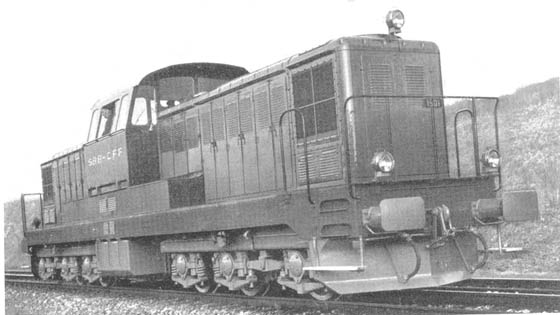
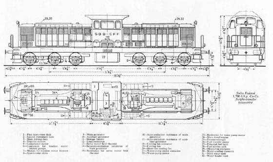
The arrival in 1955 of the first of four 1,700hp diesel-electric transfer & shunting locomotives for Swiss Federal Railways marked a contrast in their previous small scale acquisition of diesel locomotives (including two 1,200hp units from 1939).
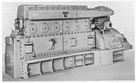
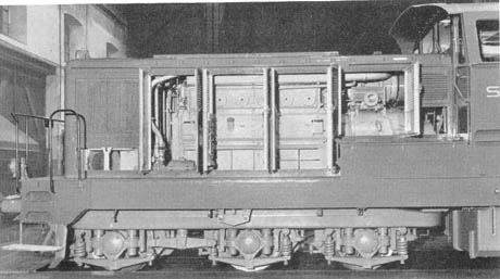
These four locomotives were each powered by two Sulzer pressure-charged 6LDA25 units with 250mm by 320mm cylinders set to a one hour output of 850hp at 850rpm, and a continuous output of 750hp at 790rpm. All the usual Sulzer features were included, the welded crankcase and underbed made up of cast steel and mild steel components, with extensions to include the generator underbed. The cylinder block was a single welded assembly, bolted to the crankcase with wet liners inserted. Thin semi-elastic pads were fitted between the locomotive underframe and the engine underbed. The seven bearing crankshaft is of heat treated carbon steel, at the front end a Sarazin vibration damper is fitted. The bearings are supported below, the top caps are tied into the crankcase transversals in such a way that they contribute to to the lateral strength of the framing, whilst having none of the conventional studs. Fine adjustment of the main bearings (to 0.10mm) is possible. A gear driven camshaft actuates the one inlet valve and one exhaust valve of each cylinder, and also the individual fuel injection pump of each cylinder. Air for the engine and for generator cooling is pulled through panel filters mounted on each side of the engine room casing.
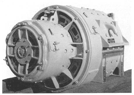
The Secheron main generators were self ventilated 10 pole machines with self & separately excited windings, an anti-compound winding and a starting winding. The auxiliary generator was carried on an extension of the main armature shaft. The main generator rating was 465/472 kW at 790/800 rpm, 1360/1400 amp & 345/330 volts. The six pole auxiliary generator had a continuous rating of 45kW from 470rpm idling speed up to the full 850rpm, having a voltage regulator set to 150 volts. The six nose-suspended force ventilated traction motors have an individual one hour rating of 146 kW, 520 amp, 310 volts, 550rpm. The traction motors were equipped with four poles with interpoles, grease lubricated armature roller bearings and white metalled plain bearings on the axle. Notable was the use of a pair of single reduction non-resilient gears on each side of the motor carcase, with the teeth inclined at an angle of 25 degrees. Gear ratio was 14 to 83. The three motors on each bogie were connected permanently in parallel. Traction motor cooling was provided through two 10.5hp Brown Boveri motors, each powering two blowers mounted either side of the motor.
Engine output was controlled by a Brown Boveri servo field regulator system, the regulator being mounted on the main generator casing. Control of engine speed & loading was through one handle, the operation of which was pneumatic. Full engine output was available between 10.5 to 37mph. Control current came from a 90 cell alkaline battery at a voltage of 110/150. The battery was arranged in three sections and was used to motor the generator for engine starting.
The underframe is completely welded up with two large rolled sections as the inner members and welded U-shaped plate forms as the outer solebars, tied together tranversely by numerous cross members. The ends of the underframe are welded into substantial drag boxes. The central cab structure and the two main end casings have welded frames of their own, though are bolted to the main underframe. The hood sections have detachable two part light alloy roofs allowing easy access to the engine generator sets.
The cab houses only a single control desk placed centrally, but has two driving positions, one on each side. All controls are located on the central desk though a number of instruments, gauges & fuses are located below the front/rear facing cab windows. On raised sections at the outside of the cab's corners are four boxes, three containing the batteries, the fourth the air compressor.
The two three axle bogies were of hollow box section fully welded up of steel plates 10 to 12mm thick, pivot supports however were of cast steel, two stiff cross members take the motor nose suspension. Suspension is of the non-swing-bolster type. Below each axlebox is a laminated spring, on each bogie the outer & center spring down each side are connected by a compensating beam, the laminated springs of the inner boxes on each bogie are independent. This arrangement in conjunction with all six motors hung towards the center of the locomotive gives least alteration in axle load when tractive effort is being exerted.
Male & female cylindrical pins & cups are used to transmit traction & breaking forces from the axleboxes to the bogie frames. The pins are secured to the bogie frame, the cups are cast integrally with the axlebox. Helical springs cushion vertical movement, horizontal forces are transmitted through a form of Silentbloc. British Timken Ltd grease-lubricated taper roller bearing axle boxes are fitted. The locomotive superstructure weight is carried at four points on each bogie, using a sandwich of steel & rubber Metalastik pillars.
The braking system uses Oerlikon air brakes with passenger & freight settings for the straight & automatic brakes. An anti-slip is combined with the air brake control. An electrically driven SLM rotary compressor provides air for two main reservoirs. Each bogie has one brake cylinder applying two blocks per wheel through fully compensated rigging. Air is also used to operate the sanding equipment and the warning whistle.
At the end of each hood were two side mounted radiators and ducting leading up to a single electrically driven fan in the roof. A main water tank is housed beneath the radiators with a header tank between the engine & cooler. The circulating pump is a 4hp electrically driven Brown Boveri unit. Control of the water temperature is through a thermostat, additionally radiator shutters could be closed in the severest of weathers. Engine lubricating oil is also cooled through certain elements of the radiator. A gear type pump in the crankcase forces oil from the sump into the cooling circuit. A similar pump directs oil from the sump through a filter into the engine system.
Two fuel tanks are slung from the locomotive underframe below the driving cab, having a combined capacity of 660 gallons. From each auxiliary generator runs a mechanically driven fuel transfer pump, lifting fuel from the main tank to each service tank situated in the hood roof. Fuel passes through two filters prior to reaching the engine.
The mechanical portions of the locomotives were built by the Swiss Locomotive & Machine Works although final fitting of the engine & electrical equipment was handled by the Brown Boveri workshops at Munchenstein (Basle). After outshopping the locomotives went to work in the Basle area, on heavy transfer freights between Basle SBB and the German Badische Bahnhof and the Rhine port area. They were also to be found in the large yards at Basle-Muttenz & Geneva, for the occasional handling of heavy military trains and as a backup when problem were encountered on the electrified network.
Haulage capacity was considered 1,150 tons at 37mph on the level, or 2,000 tons at 25mph on the level, 600 tons at 22mph up 1 in 100 and 1,100 tons at 12.5mph up 1 in 100.
Wheel diameter: 41in
Bogie wheelbase: 12ft 6in
Bogie pivot pitch: 31ft 10in
Total wheelbase: 42ft 4in
Length over buffers: 55ft 10in
Maximum axle load: 17.5tons
Weight in full working order: 104tons
Starting Tractive Effort: 73,000lb
One hour Tractive Effort at 9.3 or 4.65mph: 41,800lb
Continuous Tractive Effort at 12.4 or 6.2mph: 33,000lb
Top speed: 46.5mph
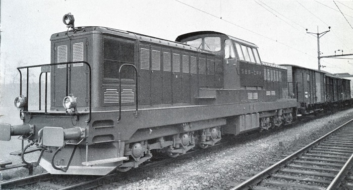
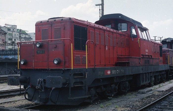
In 1960 the first of a further ten locomotives of this class was put into service numbered 1505 to 1514. These were sent to work in the Muttenz - Basle - Verbindungsbahn area on freight transfer and heavy hump shunting duties. The entire class were later renumbered to 18501 - 18514. The first withdrawl did not occur until 1999 when 18514 was retired due to extensive frost damage.
Builders Numbers:
1501 - 1504 : SLM 4092-4095
1505 - 1514 : SLM 4298-4307
Sources : Diesel Railway Traction, May 1955 and February 1961
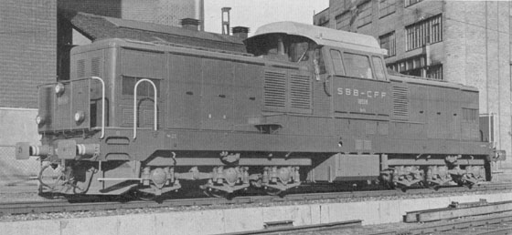
One of the second series of 1,700hp locomotives, number 18508, presumably not long off the production line.
Page updated May 15th 2003.
Last updated February 4th 2021.
![]()
Other Swiss Sulzer powered diesels:
CFF 1001 & 1002, Swiss Rail & Luggage vehicles
![]() Return to Sulzer page
Return to Sulzer page
Return to Picture menu