With regard to the NT Class it should be mentioned that (as stated elsewhere) the Sulzer-SLM collaboration affected elements of the CR NT class and also the ex-BRCW staff transfer into the Sulzer sphere. This included GC Jackson, formally chief engineer of BRCW, who would work in the London office as part of a newly formed design team. (SP)
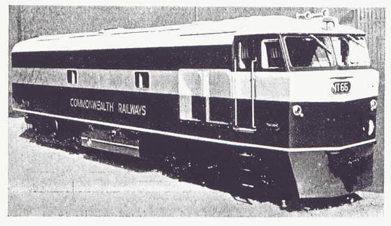
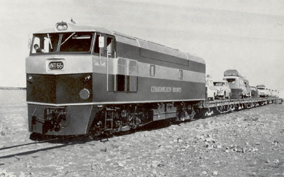
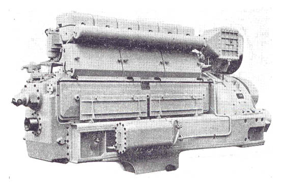
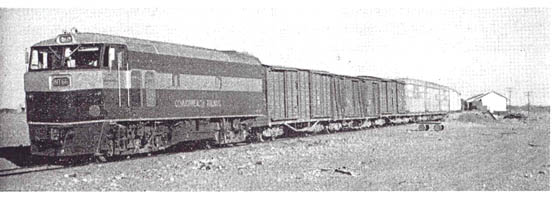
After a break of some ten years a new series of Sulzer powered locomotives were built by Tulloch Ltd, Rhodes, NSW for Commonwealth Railways, again using a six cylinder engine, though sporting considerable improvements with a sixty percent increase in output when compared to the CR NSU class. The power unit was now the 6LDA28C, a six cylinder in-line four stroke, exhaust pressure charged, intercooled unit, with a bore of 11.02in and a stroke of 14.17in. Continuous rating is 1,400hp at 800rpm, the one hour testbed rating was 1,540hp at 800rpm. The power units were built at Vickers Ltd Engineering Group, Barrow, United Kingdom.
The cylinder block is of the wet liner type with a heavy section top plate. A single camshaft on the outside of the bank operates the valve gear and fuel injection pumps. Removeable full length fibreglass/steel inspection panels give access to the crankcase and fuel pumps. The crankcase is an integral structure made up of a series of transverse cast steel members welded to mild steel fabricated longitudinal plates, a cross member is fitted at each main bearing position. Supporting the structure are box form side girders which extend out to carry the main generator.
The crankshaft is of heat treated alloy steel, fully machined with balance weights bolted & locked in position. A Holset vibration damper is fitted to the free end of the crankshaft, which permits unlimited choice of engine speed over the full working range. Individual cylinder heads are of alloy cast iron, with one inlet and exhaust valve per cylinder, the injector being fitted centrally.
Connecting rods are of H-section nickel-chrome forged steel, machined on all surfaces to reduce weight, avoid irregularities and permit accurate balancing. The rods are drilled to allow for the passage of lubricating oil from the big ends to the small ends and for cooling the pistons. The pistons are aluminium alloy, machined inside & out.
Traction & electrical equipment were supplied by AEI (UK) Ltd. The main generator is an AEI Type TG.5302W, driven through a solid coupling, the shaft being supported by a single bearing at the outer end. Beyond this bearing runs a shaft extension to drive the auxiliary generator. The armature core is built up from magnetic sheet steel laminations. These are press fitted on a spider, held in place by the end plates. A heat treated hot rolled medium carbon steel shaft supports the spider. The armature coils are former wound and consist of glass covered copper strip which is mica taped after forming, and so arranged that any two conductors have mica between them.
The commutator is constructed of hard drawn copper bars, insulated from each other by micanite & secured over almost their whole length by steel anchor bars which are welded to support rings. This 'Pollock' type construction ensures rigidity in a circumferential direction and stability of the copper segments radially.
The magnet frame is fabricated from high permeability steel, large openings with removeable steel covers allow for inspection of the commutator & brush gear. The ten main poles are made up of soft steel laminations secured by rivets, the ten compoles are made of solid steel bar.
The auxiliary generator is used to charge the batteries, locomotive control, lighting and other electrical requirements. It is driven from the traction generator and so configured that normal regulated output voltage is obtainable at engine idling speed.
An auxiliary drive gearbox is fitted on the end frame of the main generator, which accomodates three seperate drives, one vertically above the main generator shaft, the other two below to the left & right. The auxiliary equipment is situated at either end of the engine room, no internal bulkheads were fitted, creating a very open space.
The combined pump set features the main water circulating pump, the fuel transfer pump and the auxiliary lubricating oil pump. The latter is essentially a priming pump but can provide a supply of oil to the bearings should the main engine driven pump fail.
The six AEI Type 253AZ traction motors are designed for axle & nose suspension. They are connected in permanent series pairs across the generator. The frame is a casting of high permeability steel annealed to releave casting stresses. The gears are enclosed in a welded sheet steel case, the gear ratio is 92/19. The motor pinion drives a solid spur gearwheel mounted on the axle. The pinion is manufactured from an alloy steel forging, it is case hardened after tooth cutting. The gearwheel is machined from a carbon gear steel forging which is heat treated after tooth cutting.
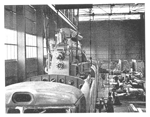
The superstructure is of a fully integrated stressed skin body construction produced by Sulzer in collaboration with the Swiss Locomotive Works (SLM); a 12-gauge outer skin is stiffened by rolled section vertical & horizontal members. The power equipment is carried on transverse members rigidly connected to the side girders. End loadings are transmitted from the coupler through specially constructed triangular girders into the main framing. Buffing loads of 150 tons at the coupler were designed for without deformation. The bulkhead between cab and engine room is three inches thick and heavily insulated. In order to achieve the required minimum height the engine/generator set is installed at a lower level than the floor, precluding the use of a conventional underframe. The complete body is pressurised against the ingress of dust, sand and other fine particles. Two hydrostatically driven fans draw air in from the roof and deliver it to the compartment through oil wetted metal filters.
Bogie construction is from pressings and castings welded together, allowing strength and integrity for these 3ft 6in gauge diesels. All welds are placed in the neutral axis. The bogies are of the fixed bolster type but the kingpin is cushioned in rubber. Axleboxes are guided by radial arm suspension links, each of which is fitted with Silentbloc rubber bushes. Lateral oscillations and nosing are dealt with by rubber secondary suspension springs, these also reduce the weight transfer when the locomotive is exerting high tractive effort. With the rubber side bearers in shear there is no friction between the bogie and the locomotive body when traversing curves. The axle loadings are tapered to equalise the stress on the rail at each wheel. An inter-bogie mechanism - two yoke arms supported on rollers - allow the bogies to take the most favourable path when running through curves in an attempt to minimise rail and flange wear.
Specifications called for the capacity to haul a trailing load of 750 tons over the ruling grade of 1 in 80 at a speed of not less than 9mph. When delivered greater trailing loads were possible; 940 tons at 11.2mph or 1,060 tons at 9.8mph.
Gauge: 3ft 6in
Wheel arrangement: Co-Co
Wheel diameter: 37in
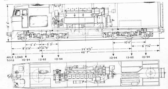
Bogie Wheelbase: 10ft 6in
Bogie Centres: 29ft 9.5in
Length over headstocks: 46ft 7in
Maximum height: 12ft 3in
Maximum width: 8ft 7.25in
Weight in working order: 69tons
Maximum service speed: 50mph
Maximum starting tractive effort: 57,000lb
Continuous rating: 34,600lb at 11.2mph
Maximum axle loading (tapered): 10.94/12.62/10.94 tons
Gear Ratio: 92/19
Fuel Capacity: 700 gallons
Minimum curve radius: 5.7 chains
| Locomotive | Builders Number | Delivered | Withdrawn |
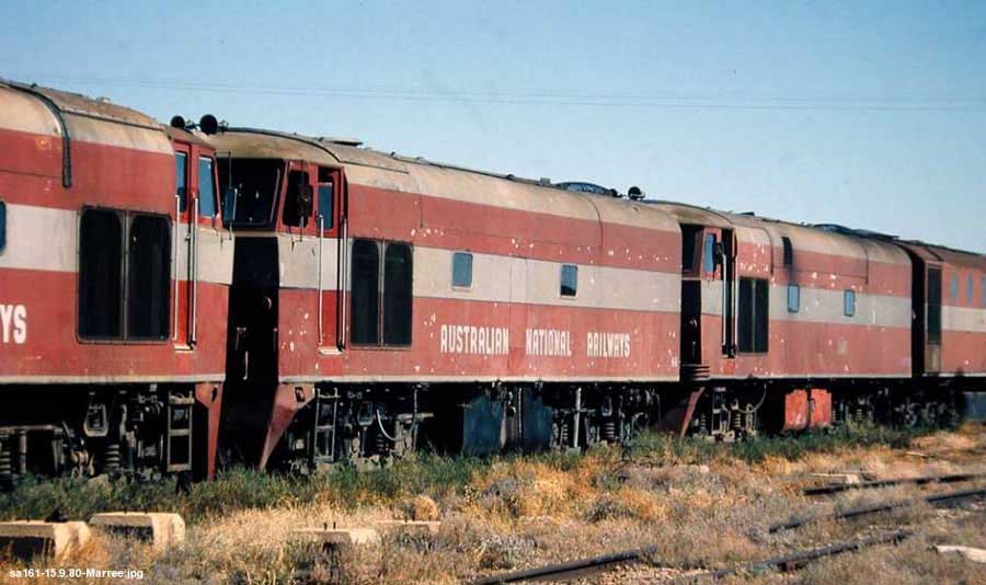
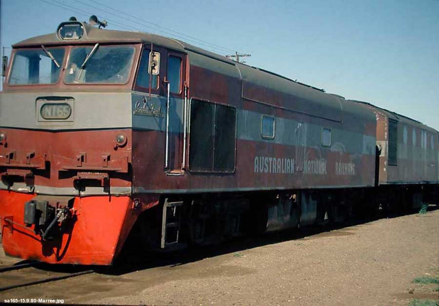
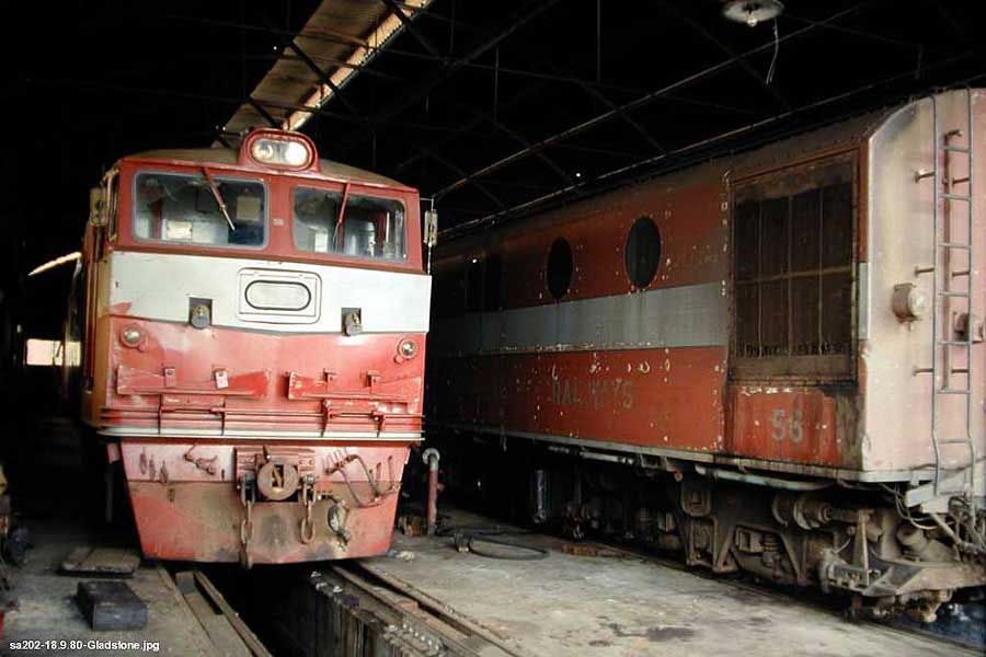
| NT65 | 037 | April 24th 1965 | 1981 | NT66 | 038 | June 18th 1965 | 1980 | NT67 | 039 | August 4th 1965 | ?? scrapped Gladstone 1989 | NT68 | 040 | November 11th 1966 | 1978 | NT69 | 041 | November 28 1966 | 1988, scrapped Port Lincoln Aug 1990 | NT70 | 042 | January 11th 1967 | 1975 | NT71 | 048 | December 1st 1967 | 1975 | NT72 | 049 | March 21st 1968 | ?? 1983 | NT73 | 050 | April 18th 1968 | 1988, scrapped Port Lincoln Aug 1990 | NT74 | 051 | June 1st 1968 | ?? scrapped Port Lincoln 1989 | NT75 | 052 | June 28th 1968 | November 1972 | NT76 | 053 | August 12th 1968 | September 1989 - Preserved | NT77 | 054 | September 25th 1968 | 1978 |
Notes
NT65 was named 'Gordon Freeth' on May 12th 1965.
NT68, NT70, NT71 & NT75 all sustained damage in an accident at Darwin during November 1972. NT70 & NT71 were removed to Port Augusta shops for possible repair, but were written off in 1975. A report on this accident, from J.Y. Harvey's "The Never-Never Line" reads as follows:
"The accident happened around 5pm on Saturday November 4th 1972 in Darwin yard (Frances Bay). A southbound mixed train led by NT70 was waiting in the yard, ready to depart when a loaded iron ore train from Frances Creek arrived to unload. The iron ore train's locomotives had been detached at Parap (just over two miles south of Darwin) for servicing, and replacement units NT75+NT71+NT68 had been attached to the train. The brake system hoses on the iron ore train had not been connected, and no brake test had been done. When the iron ore train's driver tried to slow the train as it entered Darwin yard, he found he had no brakes. The driver and observer jumped at 30mph, and the iron ore train ran head on into mixed train. No-one was killed or injured, but the impact was massive, destroying NT75, the relay van on the mixed train and 23 ore wagons. Heavily damaged NT70 and NT71 were stored at Port Augusta pending repair, but were eventually written off without being repaired. NT68 was only slightly damaged, and was returned to service on the North Australian Railway".
NT69 was scrapped at Port Lincoln during August 1990, whilst being cut up fire broke out and spread to nearby NT73 igniting fuel remaining in the fuel tank!
All locomotives at one time or another worked over the Central and Northern sections.
Sources
Railway Transportation - September 1965
The Railway Gazette - July 2nd 1965
The Never-Never Line (the story of the North Australian Railway) - J.Y. Harvey, 1980 Melbourne, Hyland House.
![]()
Other Australian Sulzers:
Commonwealth Railways NSU Class
![]()
Page added March 25th 2003.
Page updated June 16th 2023.
Return to Sulzer page
Return to site menu