Just prior to the start of World War Two the Roumanian State Railways (Caile Ferate Romane or CFR) had taken delivery of a twin unit close coupled 2-Do-1 + 1-Do2 locomotive of 4,400hp. It proved to be a success and further orders would no doubt have been forthcoming had not the war intervened. It was a considerable length of time after the end of the hostilities before the CFR could contemplate major steps towards dieselisation. During the mid 1950's the prospect of financing with the availability of new diesel locomotives that could match the capabilities of the pre-war twin unit fell into place.
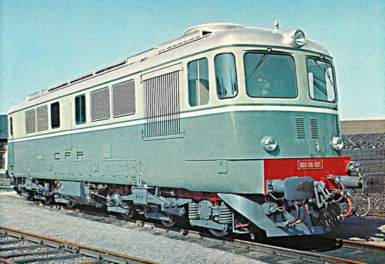
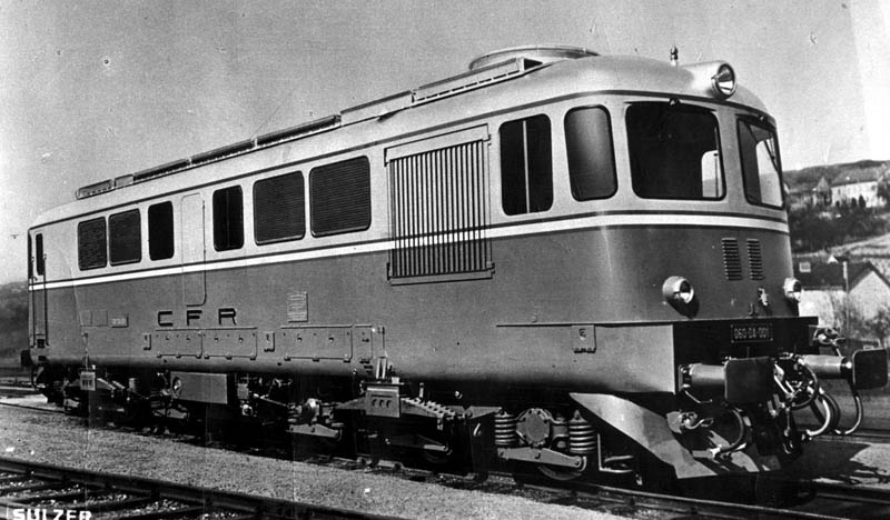
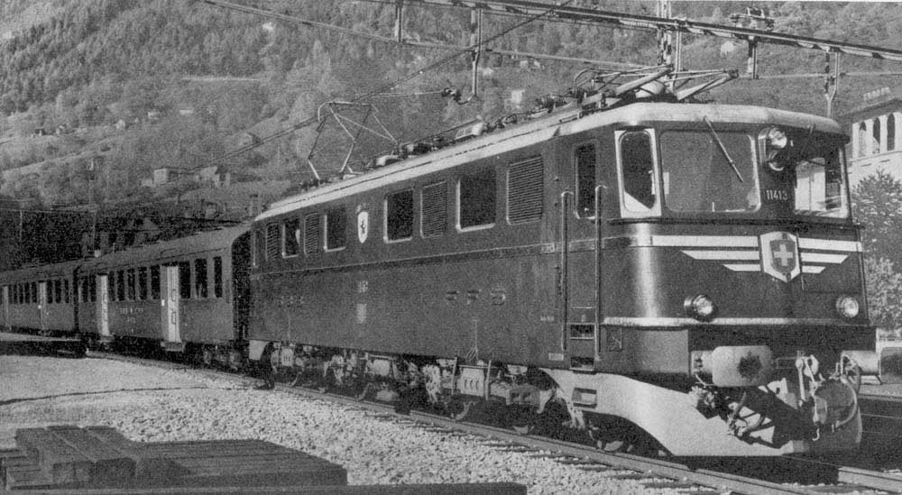
The twin unit concept had moved on, the designs now called for a six axle unit that had similar horsepower to one half of the twin unit but had much improved adhesion weight. Initially six locomotives were ordered, built in Switzerland by a consortium of Sulzer Brothers, Winterthur; Brown Boveri & Co, Baden and the Swiss Locomotive and Machine Works (SLM), Winterthur. Although the mechanical portions were built by SLM the final erection and installation of the electrical equipment was done at Brown Boveri's Hauenstein shops. The locomotives then returned to Winterthur for final adjustment & testing. This first order was slotted into the order for the Ae 6/6 series locomotives, to which they bear a striking resemblence externally (see view towards bottom of page).
The power unit was a twelve cylinder twin bank four stroke Sulzer 12LDA28 fitted with a single Sulzer exhaust-gas turbo-charger. The UIC rating of the engine was 2,300hp at 750rpm, though one engine on a test bed had been run at 2,500hp at the same speed. For the conditions on the CFR (altitude to 3,450ft and temperatures to 95F) the output was set at 2,100hp at 750rpm. Cylinders were 280mm by 360mm (11in by 14.2in), piston speed was 29ft per second, charging air pressure was 25lb per sq in. Dry weight was 46,250lb. The two banks of six cylinders were arranged vertically and parallel to each other, each bank having its own crankshaft. The two crankshafts drive the generator through a common gear at a speed 1.44 times faster than that of the engine.
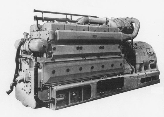
Crankcase and cylinder block were welded from cast steel sections and steel plate and are bolted together. The crankcase carries the main bearings in U-shaped transversals which are extended in a straight line into the cylinder block and transmit the gas pressures directly to the bearings. Extended longitudinal supports from the crankcase carry the gearing and generator. Four groups of rubber mountings carry the entire unit on the locomotive frame. The three gear wheels are of chrome-nickel steel, manufactured by the Maag process, they are hardened and ground. Each cylinder has its own individual water cooled cylinder head of cast iron, into which one inlet valve, one exhaust valve and the fuel injector are fitted. There is one fuel injection pump per cylinder. Cylinder liners are cast iron and are water cooled. The two-piece pistons are of light alloy. The chrome-nickel steel connecting rods are fully machined and are drilled longitudinally to convey lubricating oil to the gudgeon pin bearings and for cooling the pistons.
The small end bearings are of the one piece steel-backed lead-bronze type, the big-end bearings are of a two piece, steel-backed lead-bronze lead-flash pattern. The two camshafts are driven from the upper gear shaft. The alloy steel crankshafts with balance weights on the webs are provided with Holset vibration dampers and each is carried in seven plain bearings with two-piece steel-backed lead-bronze lead-flash bearings shells. Removeable side covers allow for easy inspection of the main & big-end bearings.
The single Sulzer exhaust-gas turblo blower is mounted on the gear housing, its shaft runs in plain bearings which are lubricated by the pressure lubrication system of the engine.
The generator set comprised a ten-pole d.c. main generator and an eight-pole d.c. overhung auxiliary generator. Maximum current for the main generator is 3,700 amp, a one hour rating is 2,700 amp, continuous current is 2,460 amp, a maximum voltage of 890V and a rated output of 1,080rpm. The auxiliary generator has a continuous output of 75kW and a steady tension of 175V. Weight for the combined set is 16,600lb with a maximum diameter of five feet, length over coupling flange is 64.4in. The six traction motors are six pole d.c. series-wound units with the drive taken up by a pinion to a resilient gear wheel on the axle. Each motor has a one hour rating of 194kW at 900amp, a continuous rating of 200kW at 820amp, a maximum starting current of 1,230 amp. Individual motor weight is 4,620lb. The reduction gears have a ration of 15:69. Force ventilation is provided, the motors are also self ventilated with a built in fan which maintains a higher pressure within the motor, preventing the ingress of dust & dirt, possible under certain operating conditions.
Cooling equipment was provided by Behr of Stuttgart. Two coolers with interchangeable elements and a fan utilised the well known Behr hydrostatic fan drive & control. Cooling air was drawn in through louvres in the body sides. A heat exchanger allowed the engine lubricating oil to be cooled through the engine cooling water circuit. This arrangement makes both oil & water temperatures mutually dependent, allowing only the regulation of the water temperature to maintain both properly. The hydrostatic fan regulator monitors water temperature, at a pre-determined level oil pressure in the hydrostatic circuit increases so accelerating the fan, at the same time the louvre openings are increased. The cooling water pump is designed to run after the power unit is shut down, to prevent heat accumulation in the system. In the Roumanian locomotives, to avoid the possibility of the cooling water from freezing, a Vapor heating unit was installed in the cooling circuit. When conditions demand it (an oil temperature below 30C) this unit can pre-heat the lubricating oil.
The lubricating oil pump was driven from the damper end of one of the crankshafts, delivering oil from the sump to the heat exchanger, then passing through the Knecht main oil filter. Here the oil line split, one line taking oil to various points on the engine and gearing, the other to the turbo-charger. An electrically driven auxiliary lubricating pump feeds the governor with oil direct from the sump. This pump operates prior to engine start-up, to fill the system, and after engine shut-down to prevent the formation of carbon in the oil-cooled pistons. Combined with this pump is a fuel transfer pump which draws fuel from the main tank through a coarse strainer to the service tank. The fuel then passes through Knecht strainers and fine filters before reaching the injectors.
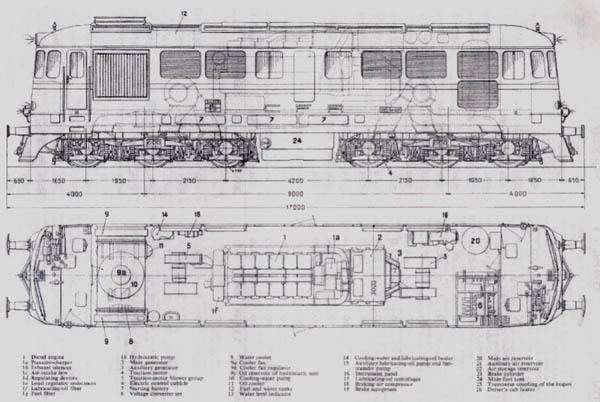
The underframe, sidewalls and roof form a self supporting warp free integral welded construction. Despite this the underframe is still of substantial construction, the main solebars are of I section thirteen inches deep. Battery boxes and sand boxes are fixed to the side of the underframe. Traction motor cooling air is also routed through ducts welded into the underframe. Each side of the body contains an access door that permits removal of small components, the engine/generator set can be accessed through removeable roof panels. Smaller covers within the roof allow for removal of the cylinder heads & pistons. Each end of the body carries a cab, access is from one side only, the driving position is on the right side of the cab. The cab floor is of treated wood. The cabs are insulated against noise from the engine room by special sound insulation partitions and double windows. The cab roof is also clothed with a special insulation against noise & heat. The roof and side-walls of the body are sprayed with an anti-drumming compound. A toilet, wash basin and water reservoir are fitted in the locomotive body.
An 880 gallon fuel tank, of welded construction is bolted to the underframe between the bogies. Additional capacity is also available from the service tank.
The bogies are a simplified adaptation of the well known SLM type used by the Co-Co Gotthard 6,000hp electric locomotives of the Swiss Federal Railways. Superstructure weight is transmitted through lateral bearers to the double inverted laminated springs, which are arranged longitudinally on each side of the bogie. Swing bolsters slung from the bogie frame connect these springs. Traction, braking & buffing forces are transmitted through a king pin between the bogies & superstructuure. Two vertical cylindrical guides bolted to the bogie frame hold each axlebox. The axlebox bearings are of the SKF self-aligning roller-bearing pattern.
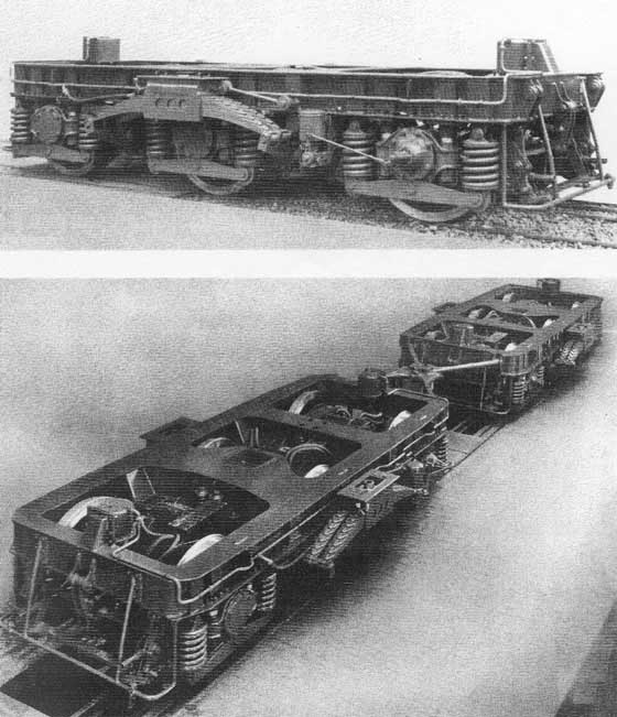
In order to minimise flange wear when running through curves the bogies are connected by a transverse coupling, allowing the bogies to take the most favourable position through curves. No tractive effort forces are transmitted through this mechanism, which is simply a series of rods, dashpot and helical springs. Friedman flange lubricators are also fitted to the wheels on the outermost axles Wheel diameter is 43.5in with cast steel centres.
Brake equipment comprised of an automatic Knorr KSS brake, a direct-acting Oerlikon brake for the locomotive alone and a Brown Boveri-Charmilles anti-slip brake. Two 12in diameter brake cylinders can be found on each bogie which act through compensated rigging to clasp blocks on every wheel. The hand brake acts only on the first axle and one wheel of the center bogie. Air required by the braking system and other pneumatically operated equipment was provided by an Oerlikon two-stage compressor with intermediate cooling. The main air reservoir, service air reservoirs, brake compressor and control valves were situated behind the number one cab.
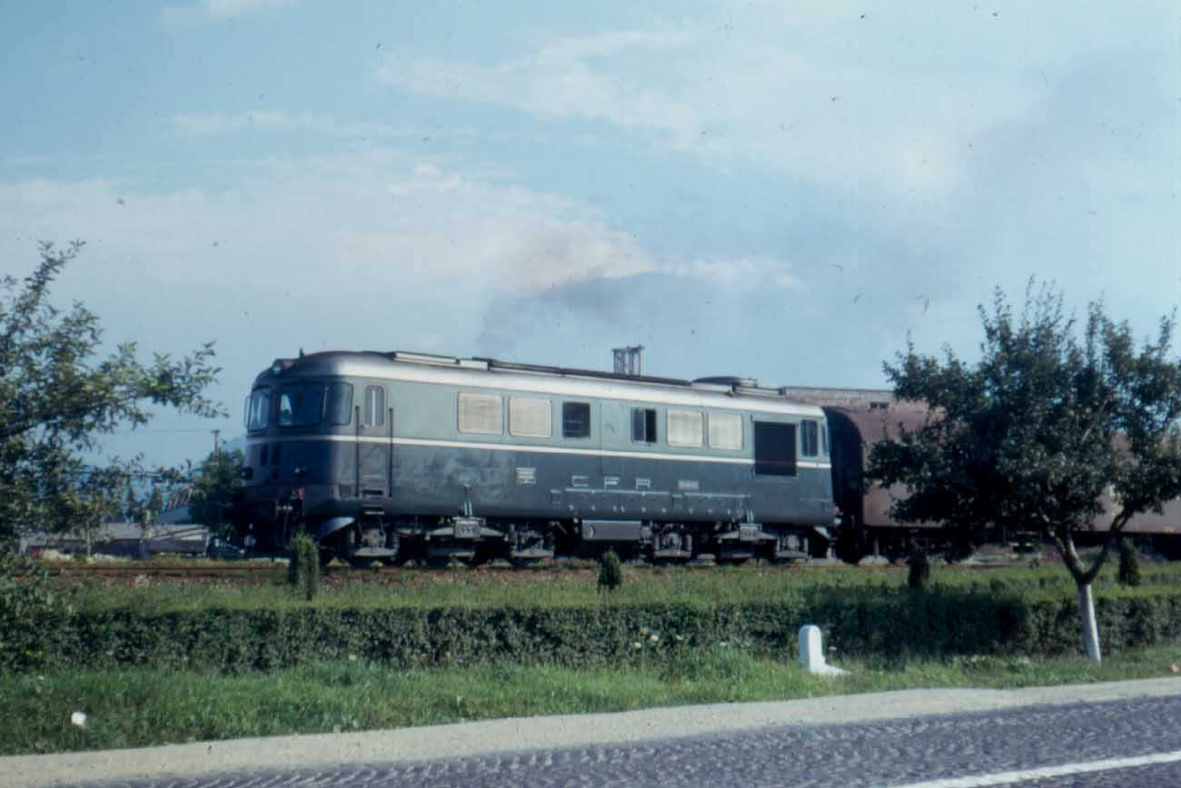
All six of the Swiss built locomotives underwent acceptance trials of a minimum 62 miles on the Swiss Federal Railways, principally the route from Winterthur to St Gall or Romanshorn. The first locomotive also made a trip up the northern bank of the Gotthard line as far as Goschenen. This involved a climb of 2,080ft over 17.8 miles with the gradient split between 1 in 38.5 & 1 in 40. With a 66 axle freight totalling 550 tons standing mostly on the steeper grade the locomotive was able to reach 13.7 mph in three minutes. Elsewhere a 94 axle freight of 1,066 tons was handled by one locomotive over the 34 mile route from Winterthur to Romanshorn. Under full power 37mph was maintained over minor gradients near Weinfelden. On the return trip, with the whole of the train stopped on the ruling grade of 1 in 83 a speed of 17mph was reached after three minutes.
Two locomotives were tested in multiple on the Romanshorn route with a trailing load of 1,227 tons. With one engine shut down the train was restarted on a 1 in 200 grade accelerating to 23mph within three minutes. These performances were equal to or better than the paper calculations established for these new locomotives.
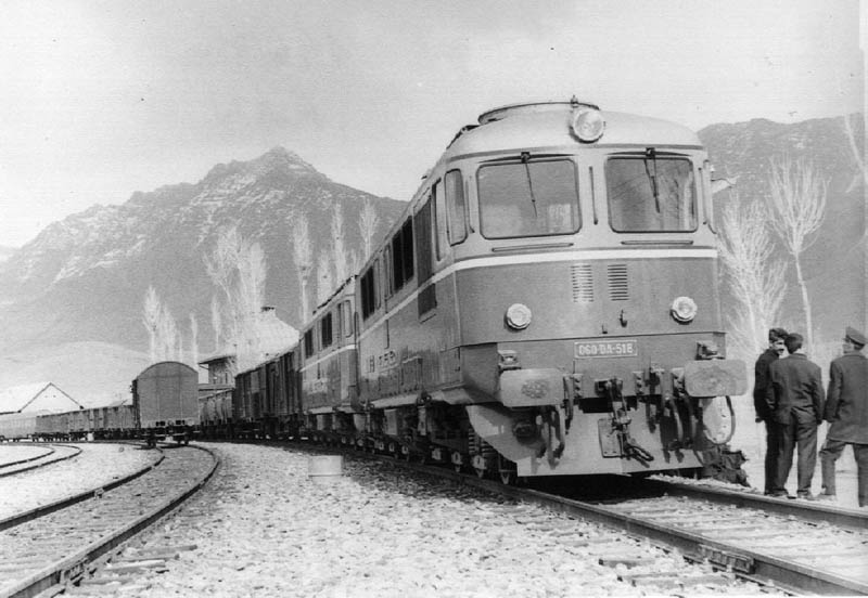
In Roumania the locomotives made round trips on 550 ton freight trains from Bucarest north over the Carpathians to Brassov. Two locomotives in multiple on the southbound leg handled 1,000 ton freight trains over Predeal summit at a minimum speed of 17.7mph. This route crests at 3,460ft after 46 miles of grades of 1 in 49 & 1in 40.
Following the delivery of these six machines a further ten were ordered, to be built in Roumania, with the diesel-electric equipment supplied from Switzerland. Further orders would continue, eventually 2,404 of the design would be built, including many for various private industries within Roumania, and the state railways of Poland, Bulgaria & China. The first ten built in Roumania, at Electroputere Craiova with order numbers 1001 - 1010 and road numbers 060 DA 007- 016 had equipment furnished by Switzerland. Orders beyond this had the power unit constructed by Masini Resita with Caromet Caransebes constructing the bogies. These initial orders were to be used on replacing steam locomotives on a variety of freight workings. Because of the excellent results from these early orders they were selected to replace the Pacific steam locomotives on the passenger routes from Bucharest to Constanta, Urziceni - Galati & Rosiori - Craiova.
The last of the Roumania order was completed in 1981, with 060 DA 1407 being allocated to Satu Mare depot.
With the CFR fleet of 060 DA locomotives just exceeding 1,400 when the last one was built, there were bound to be changes within such a large fleet. The maximum speed of the locomotive was 100 km/h but full power was only available to about 80 km/h, beyond this the useful power of the locomotive diminished. At Electroputere the traction motors were modified to permit a third stage of excitation reduction, this allowed the full power range of the locomotive to be increased to attain speeds of almost 100 km/h. Other locomotives had their maximum speed increased to 120km/hr by modifying the traction motor gear ratios - these locomotives were classified 060 DA1.
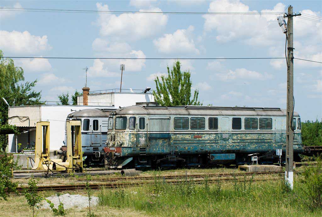
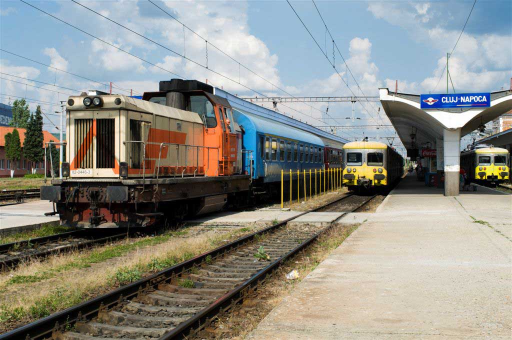
The first of the class 060 DA 001 was retired from Cluj depot in 1994, but because of its historic nature it was restored for museum display.
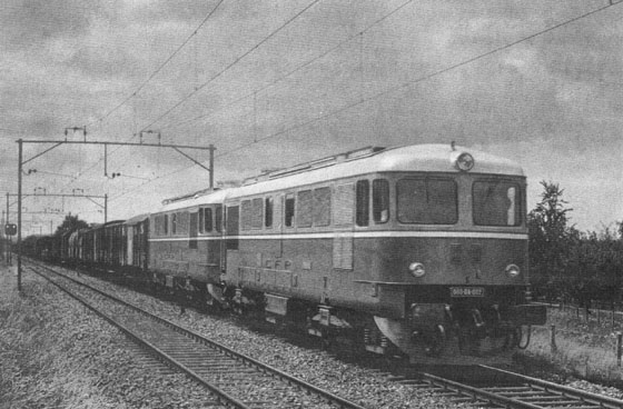
Led by 060 DA 002, two of the six Swiss built locomotives on test with a 1,200 ton freight train on the Swiss Federal Railways Winterthur - Romanshorn line.
SLM Works #'s 4246 - 4251
BBC Works #'s 6095 - 6100
Sulzer Works #'s ML585 - ML590
Based on an article in Diesel Railway Traction, November 1959.
![]()
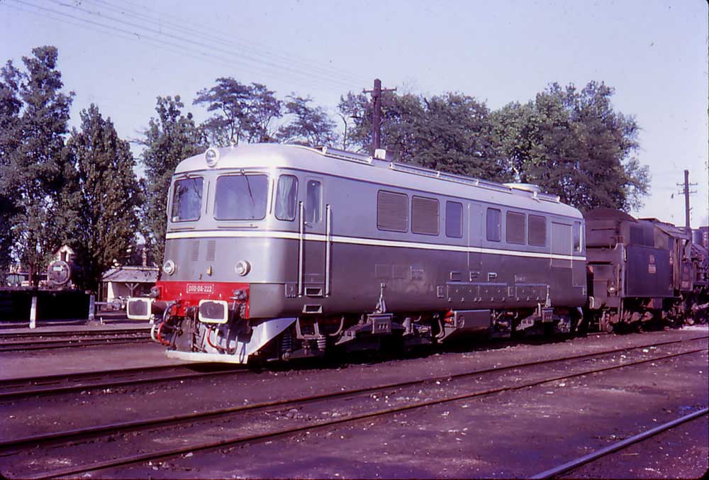
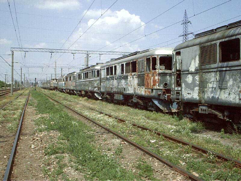
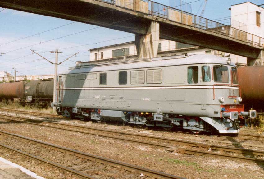
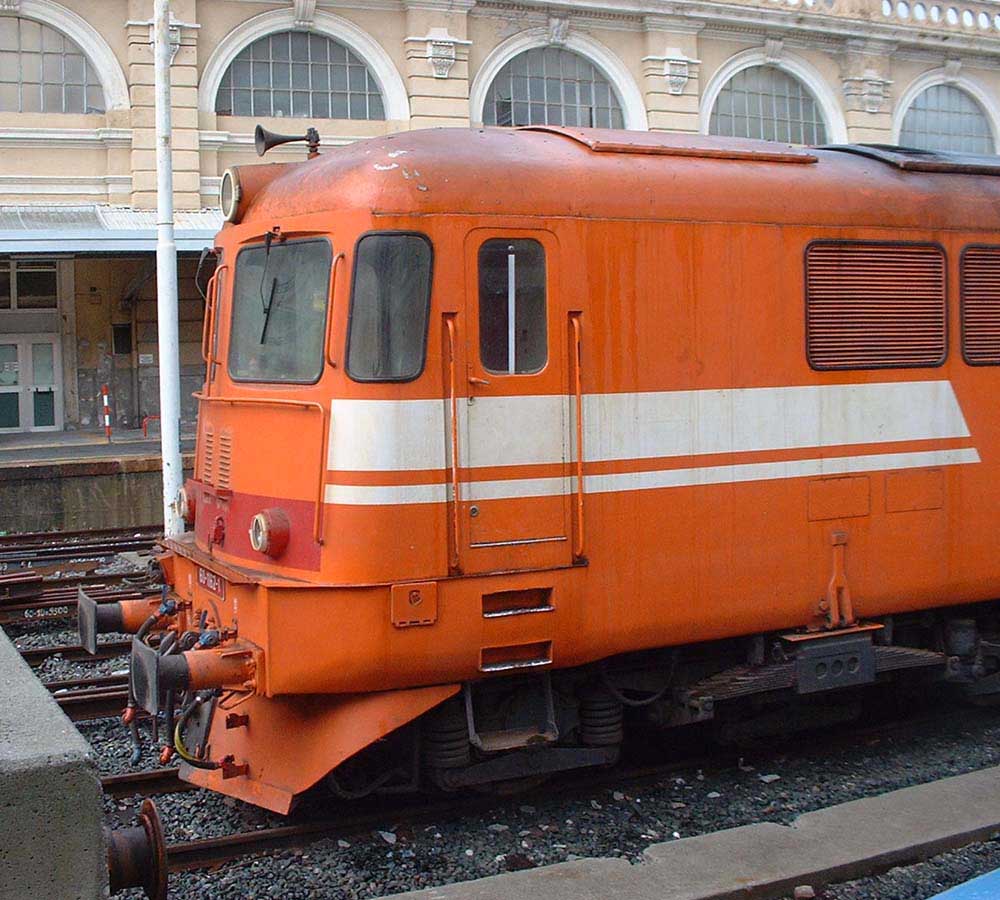
After some thirty five years of service the pioneer locomotive 060 DA 001 did not take the inevitable trip to the scrapyard. Instead because of its historic nature it was saved for preservation and is shown here surrounded by other venerable relics from the Roumanian railway system. From a cursory look at the locomotive it appears to be little changed from the black & white view above.
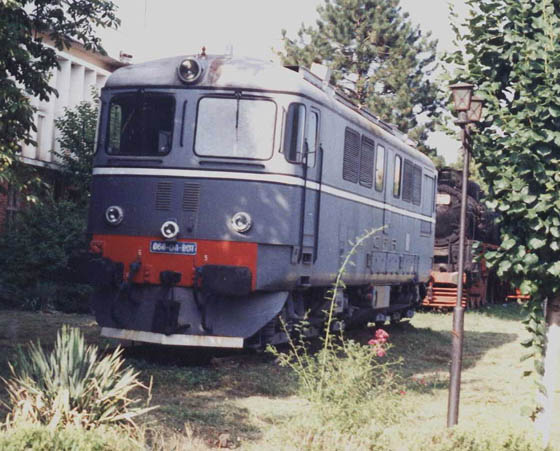
Summer 2008
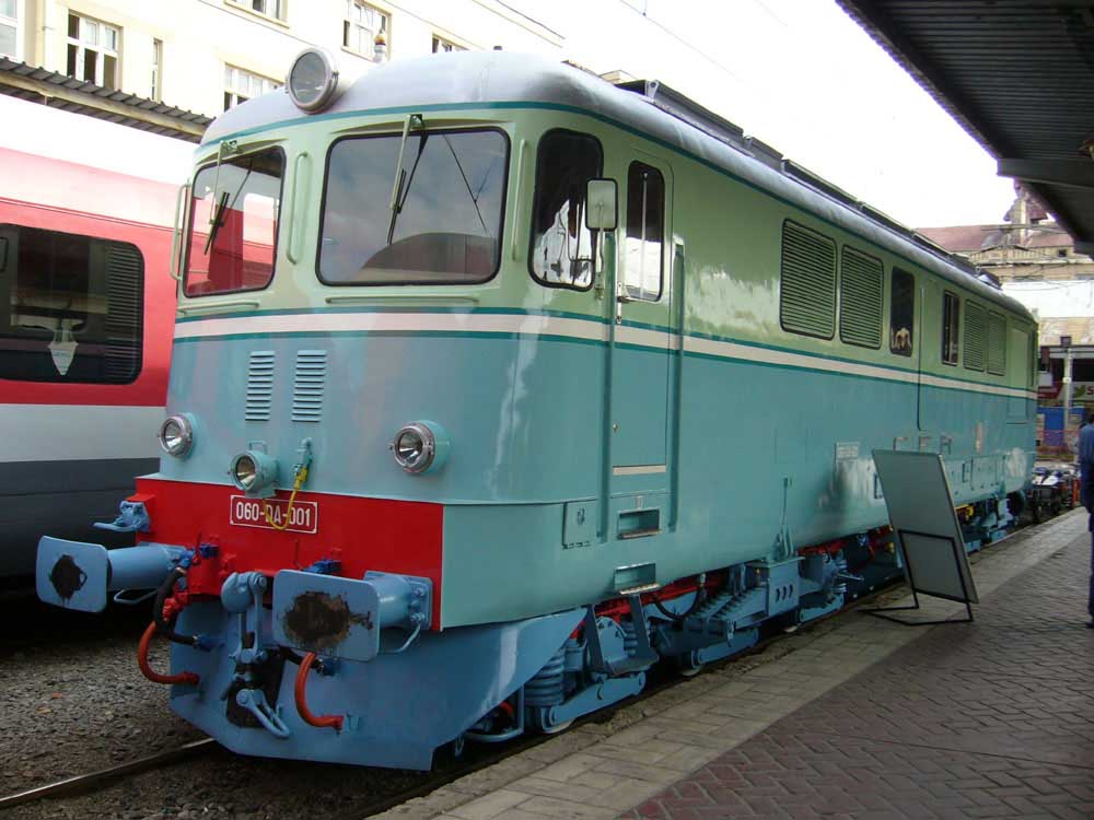
The information panel on display next to the center of the locomotive reads:
Romania's first 2100 HP diesel-electric locomotive, 1959, Original equipment and livery
The 060-DA-001 locomotive was made in Switzerland, and is part of the first series of six locomotives delivered to our country, and it is the only one still preserved of the six that were fully assembled at SLM Winterthur. It arrived in the country on 13.08.1959 and entered service on 22.09.1959 at the Brasov depot.
Saved from scrapping by a few railway history enthusiasts, this unit of historical value was exhibited in the Dej Triaj depot's yard.
As an initiative of the CFR Marfa (the company that operates freight trains), on the company's 10th anniversary, it was repaired and restored by IRLU Craiova, in order to be brought back to the technical condition and exterior aspect it had when it was built. This is the only locomotive of this type that has the original equipment and livery.
The 060-DA-001 locomotive will be preserved as a technical-historical exhibit
![]()
| Production List of the 060DA locomotives. | ||||||||||||||||||||||||||||||||||||||||||||||||||||||||||||||||||||||||||||||||||||||||||||||||||||||||||||||||||||||||||||||||||||||||||||||||||||||||||||||||||||||||||||||||||||||||||||||||||||||||||||||||||||||||
| Year | CFR (Roumania) | Private Industry (Roumania) | PKP (Poland) | BDZ (Bulgaria) | China |
| 1960 | 10 | Nil | Nil | Nil | Nil |
| 1961 | 8 | Nil | Nil | Nil | Nil |
| 1962 | 35 | Nil | Nil | Nil | Nil |
| 1963 | 59 | Nil | Nil | Nil | Nil |
| 1964 | 85 | Nil | Nil | Nil | Nil |
| 1965 | 65 | Nil | 45 | Nil | Nil |
| 1966 | 80 | Nil | 35 | 10 | Nil |
| 1967 | 76 | Nil | 35 | 15 | Nil |
| 1968 | 75 | Nil | 40 | 17 | Nil |
| 1969 | 75 | Nil | 40 | 30 | Nil |
| 1970 | 96 | 5 | 42 | Nil | Nil |
| 1971 | 86 | 9 | 40 | 8 | 8 |
| 1972 | 91 | Nil | 35 | 10 | Nil |
| 1973 | 73 | Nil | 52 | 10 | 10 |
| 1974 | 88 | Nil | 26 | 10 | 20 |
| 1975 | 77 | Nil | 8 | 20 | 20 |
| 1976 | 51 | 4 | 2 | 0 | Nil |
| 1977 | 84 | 20 | 10 | Nil | Nil |
| 1978 | 60 | 3 | 10 | Nil | 16 |
| 1979 | 49 | 4 | Nil | Nil | 43 |
| 1980 | 58 | 2 | Nil | Nil | 21 |
| 1981 | 26 | 10 | Nil | Nil | 21 |
| 1982 | Nil | 5 | Nil | Nil | 30 |
| 1983 | Nil | 15 | Nil | Nil | 14 |
| 1984 | Nil | 11 | Nil | Nil | 24 |
| 1985 | Nil | 10 | Nil | Nil | 27 |
| 1986 | Nil | 10 | Nil | Nil | 23 |
| 1987 | Nil | 9 | Nil | Nil | 26 |
| 1988 | Nil | 7 | Nil | Nil | 31 |
| 1989 | Nil | 12 | Nil | Nil | 26 |
| 1990 | Nil | 15 | Nil | Nil | 19 |
| 1991 | Nil | 7 | Nil | Nil | Nil |
| 1992 | Nil | Nil | Nil | Nil | Nil |
| 1993 | Nil | 2 | Nil | Nil | Nil |
| TOTALS | 1407 | 160 | 420 | 130 | 379 |
060DA203 was exhibited at the Leipzig Trade Fair during 1965.
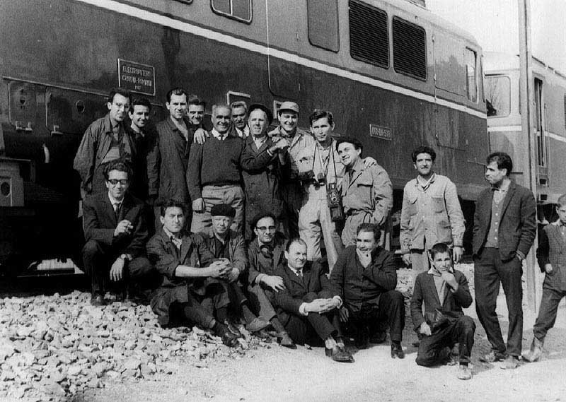
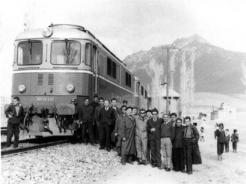
Production Views
From the collection of F Burdubus.

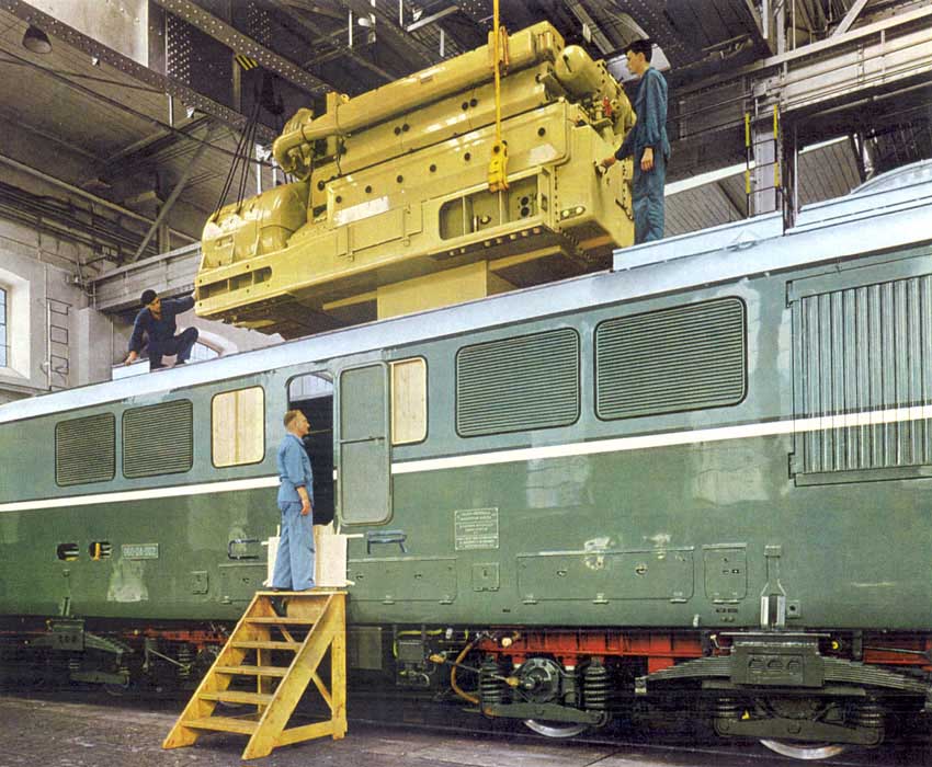
From Sulzer publicity material.

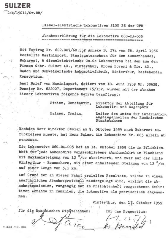
"After Mr. Director Stoian had to travel back to Bucharest on October 9, 1959, Mr. Baiasu took locomotive No.005 taken off alone. On October 14, 1959, the locomotive 060-DA-005 completed the acceptance run in the flatland with a gradient of 12%, as required by the specifications for every locomotive, on the Winterthur - Romanshorn line with a sustained gradient of 12% over a length of 3.1 km. Based on the results achieved on this trip, which are recorded in a detailed acceptance protocol, the acceptance commission declares the locomotive to have been provisionally accepted prior to the final acceptance in Romania as specified in the specifications. October 17, 1959."

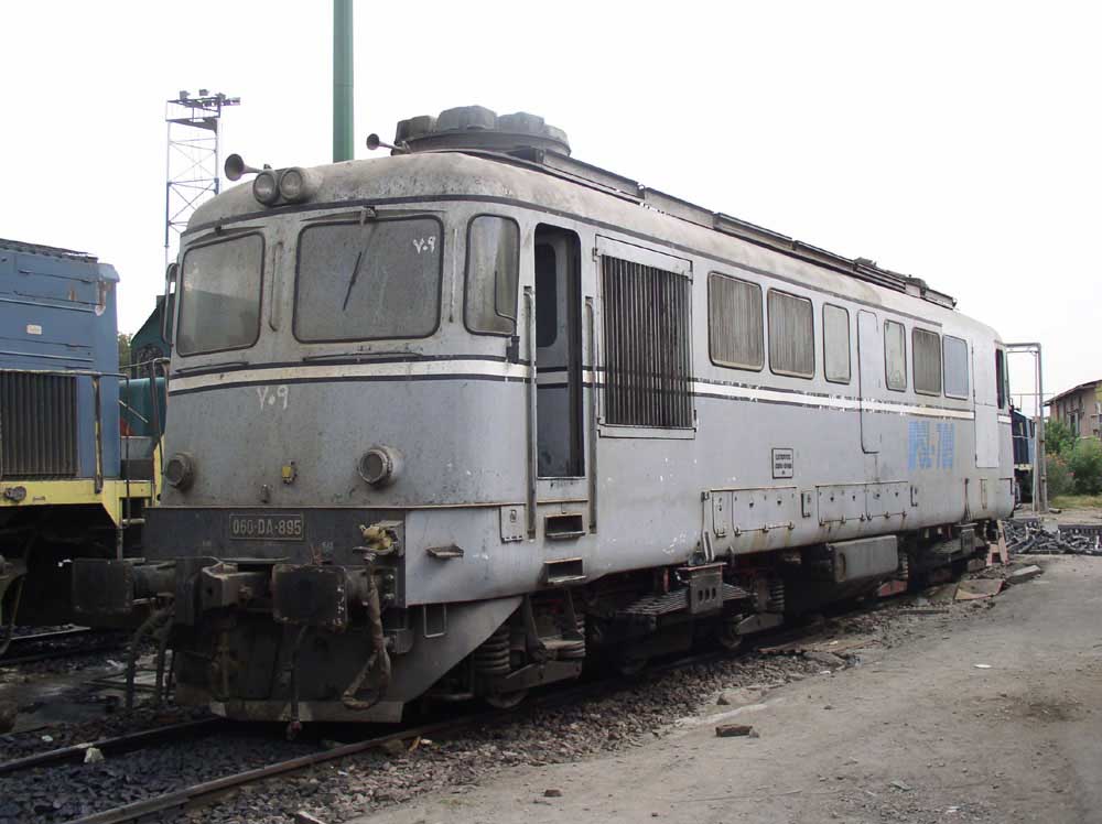
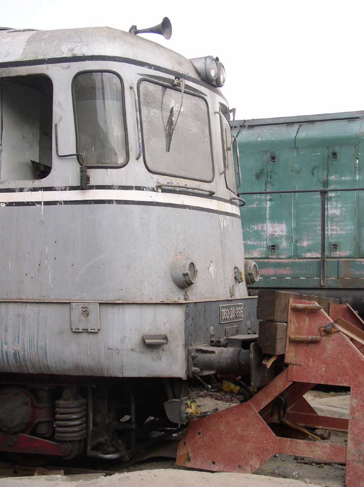
The following views, originally posted on the European Railway Server are used on this site with the permission of the photographer Andrei Frangopol, they are mostly taken around the town of Arad during the first half of 2003. The views represent both the good and the bad, some of the locomotives have reached the end of the line, whilst others continue to rack up the miles, whilst others have been rebuilt and re-engined, along the lines of some of the former British Rail Class 47's - ie save the bodies & bogies but add new power units and electrical equipment (BR's 47's became Class 57's).

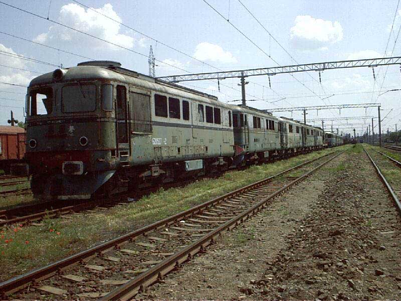
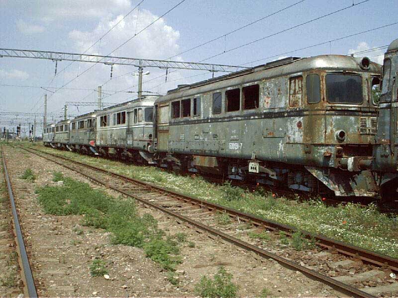
In no particular order: 60-0280-2, 62-0527-2, 60-1381-x, 60-0143-2, 60-0131-7, 60-0635-3, 60-0322-2, 60-0451-5, 60-0256-2, 60-0428-7. A couple of these locomotives date from 1964.
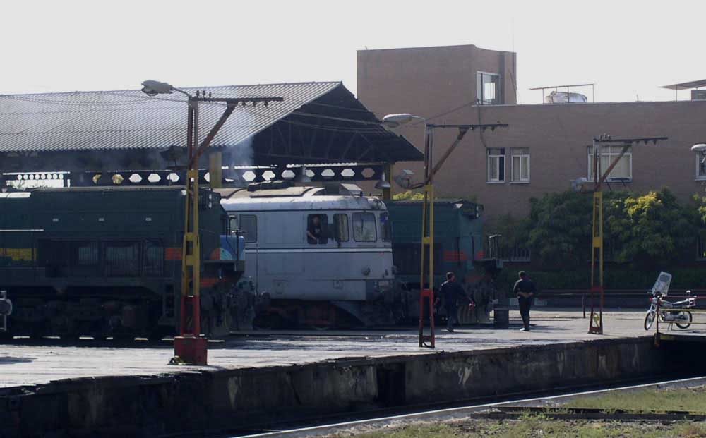
Active around Arad station.

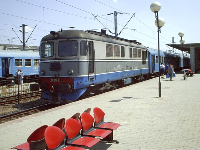
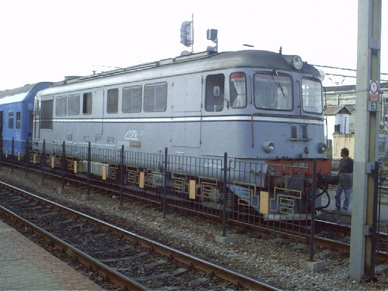
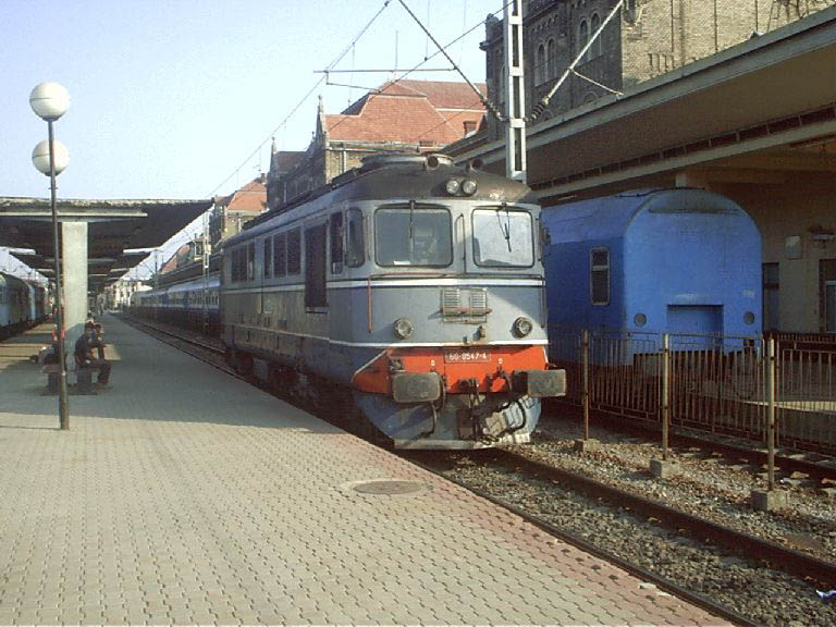
From top to bottom: 60-0449-8, 60-1013-6 & 62-1196-5 & 60-0547-4.


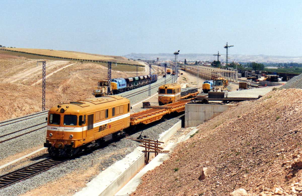
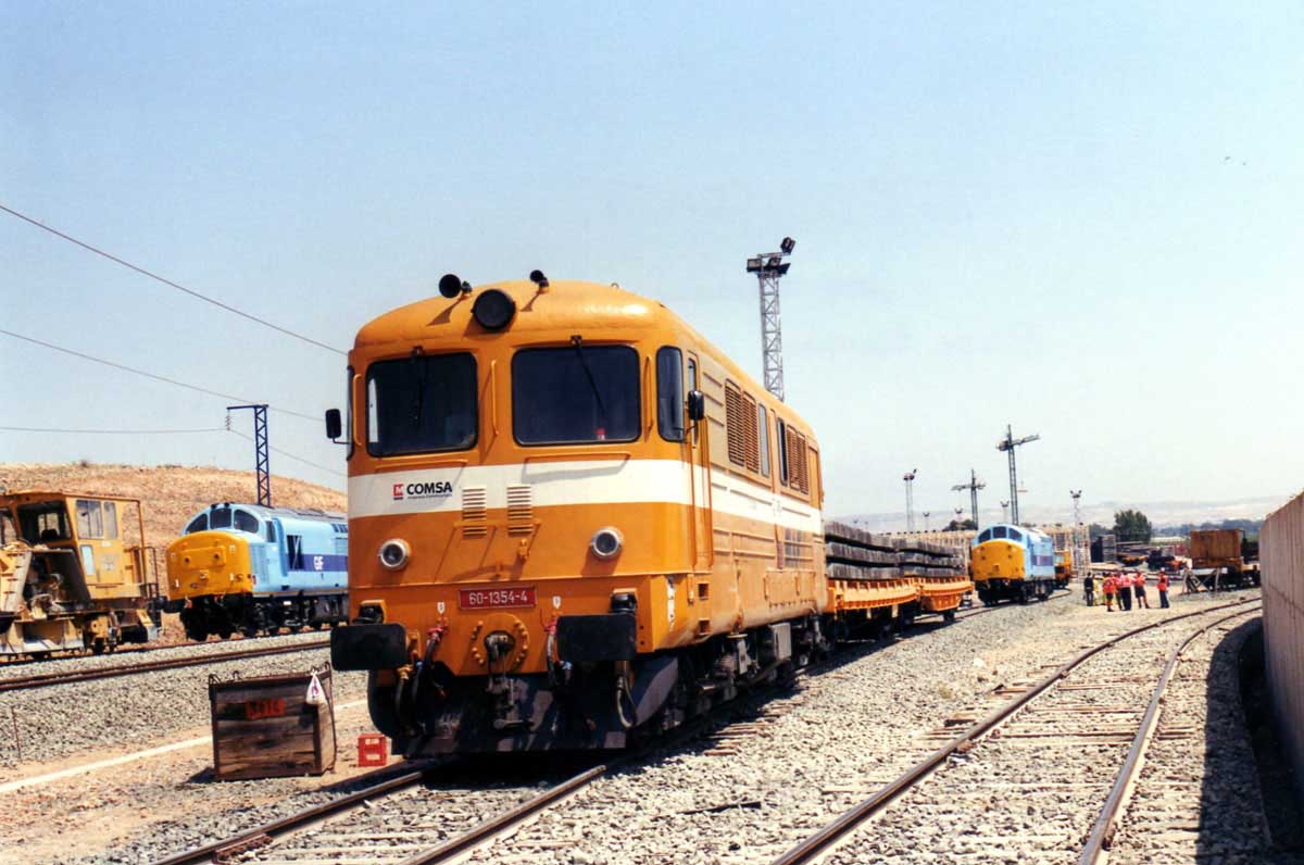
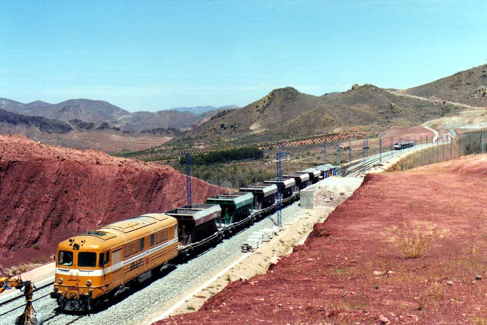
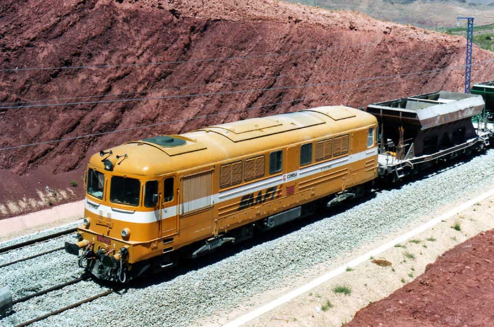
As the working lives of many of the CFR 060 DA locomotives was drawing to a close in Roumania several examples had the good fortune to escape scrapping and take up service in several other European countries including Germany and Spain. The views below show several examples of the locomotives in use on engineering trains required for the construction of high speed routes in Spain. These examples acquired the striking orange & white livery of COMSA.
![]()
The two views below come from the camera of Alessandro Albe and illustrate further re-use of CFR 060DA locomotives, this time in Italy during the construction of the high speed line built between Milano and Turino.


During 2005 about twenty CFR 060 DA class locomotives were hired to the railways in Iran, reportedly for use doubleheaded on oil trains. Below are several views of the locomotives in Iran.

May/June 2011
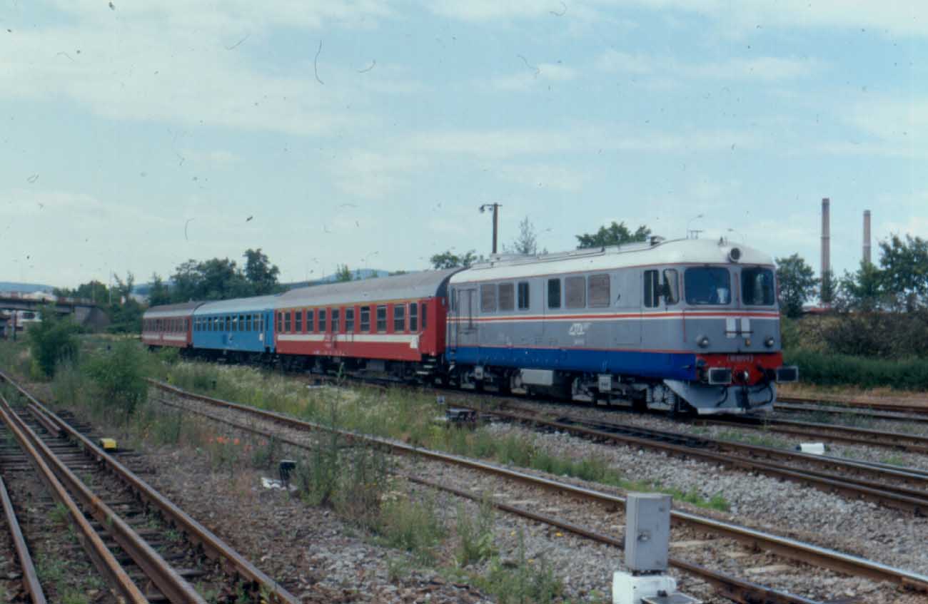
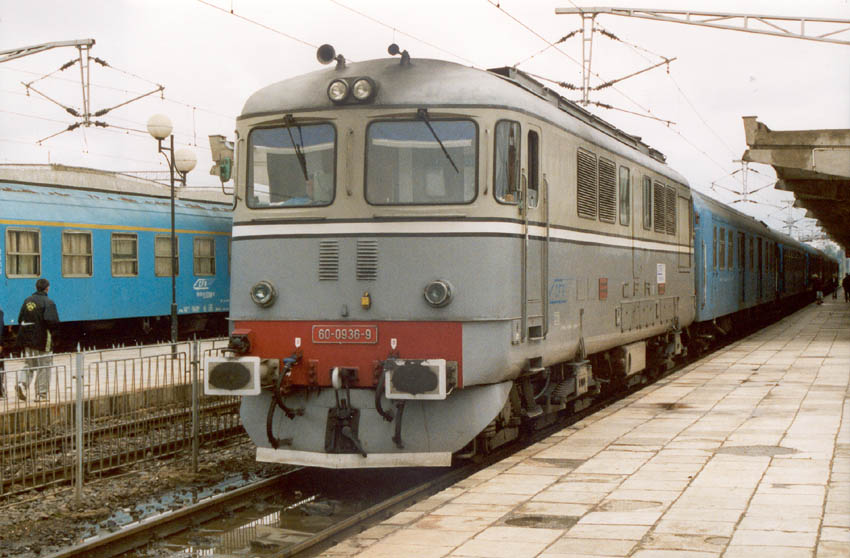
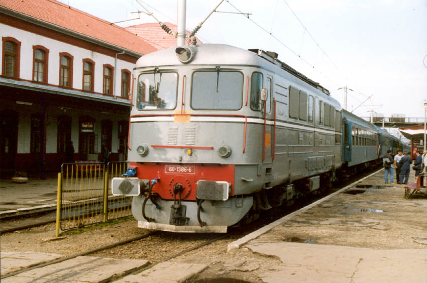
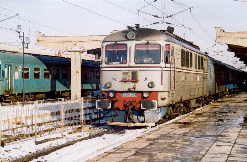
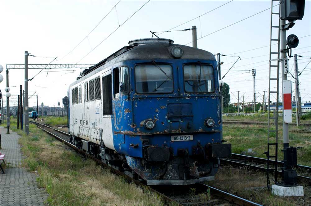
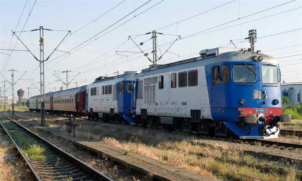
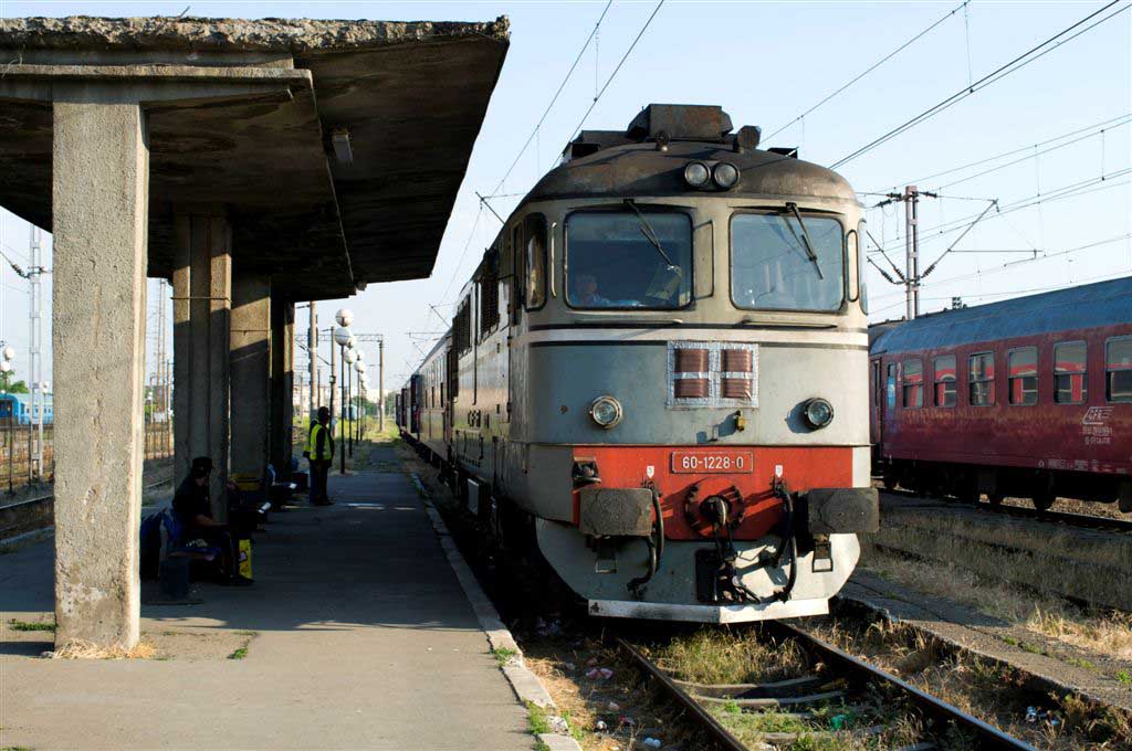
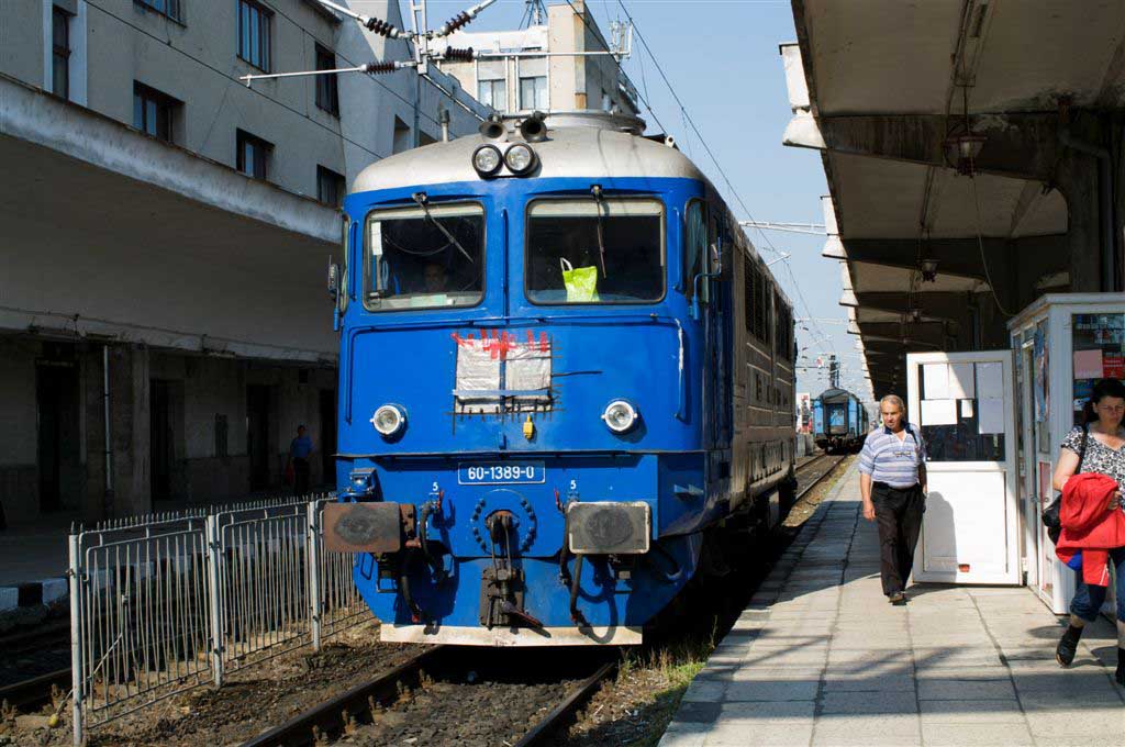
The following selection of views come from a visit by Mike Cooper to Romania during May & June 2011.
Although many of the locations are very familiar, the question must be asked - how many places in the world can you see locomotives still going strong that are 35 - 40 years old and representative of a Class with a history stretching back over 50 years? Whilst the CFR 060 DA locomotives featured in these views generally entered service from the mid-1970's onwards they have a pedigree dating back to 1959.


May 31st 2011

June 1st 2011
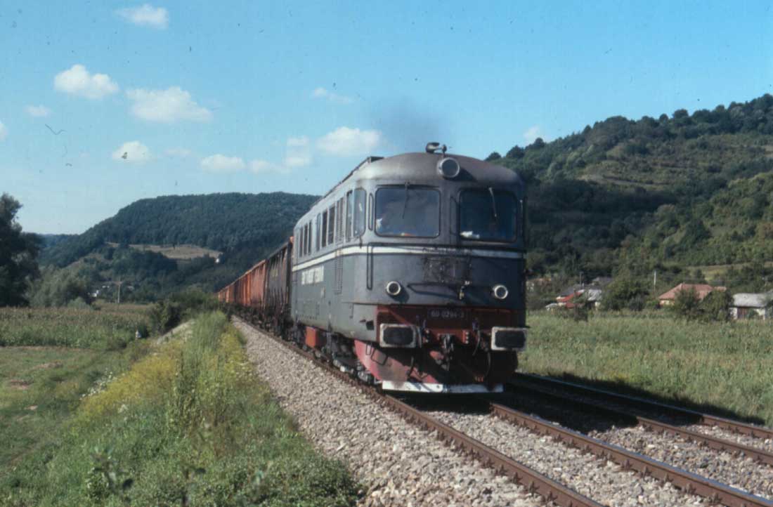
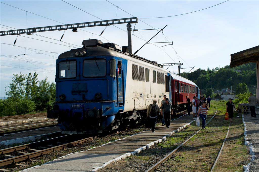
On June 2nd Mike took the train to Viseu De Sus, this important secondary line travels through the Carpathian mountains heading north to the Ukraine border. The rural scenenery was hard to miss, its doubtful if the train exceeded 25mph at any point on the journey, which is not surprising considering the official line limit was 60km/h (37.5mph).
The locomotive for the journey was 60 0881-7.
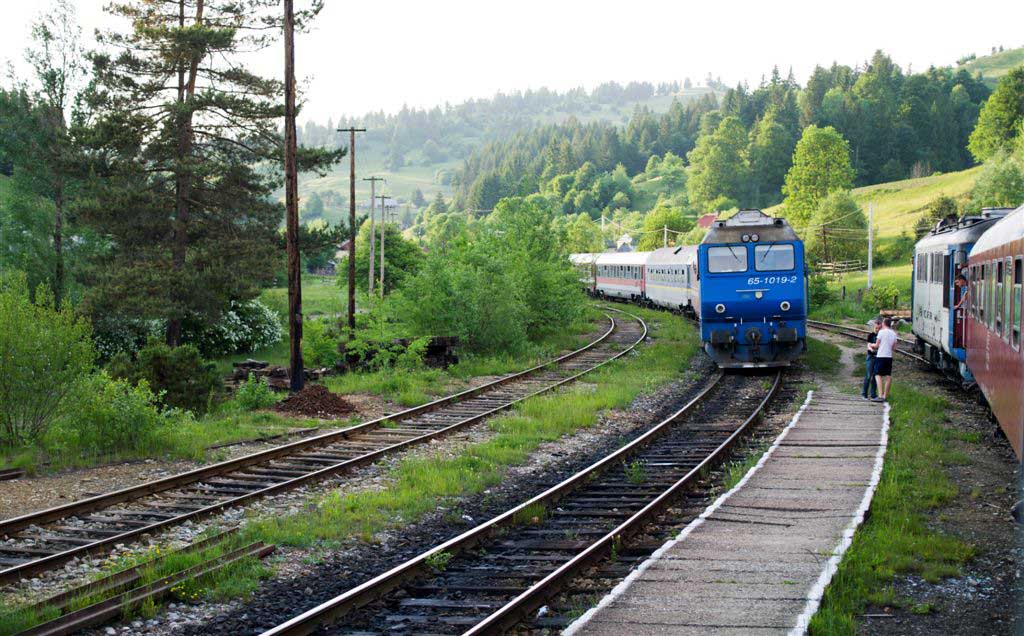

Passenger train No. 1923 was travelling from Timisoara Nord to Fiad, comprised of four bogie passenger coaches, with a length of 125 metres and weighing 191 tons and hauled by 60-1165-4. The locomotive and single crewman were from Cluj Napoca depot and had departed Fiad at 8.44am for Dealu Stefanitei under proper control. A short while later at about 9.00am the train was brought to a halt at km 28.715 when smoke was noticed coming from one of the locomotive bogies. Fire extinguishers were brought to bear on the No.5 traction motor. Prior to restarting several of the motors were isolated, but due to the gradient and with frost and leaves on the rail the train was unable to restart due to wheelslip.
The crewman was unable to contact the local stations due to flat batteries in the communication equipment but the Traffic Controller at Cluj Napoca was reached at 9.10am with the request to send another locomotive. The nearest assistance was at Viseu de Jos where 60-0720-7 was on passenger train No. 4650 operated by a driver and trainee assistant, both from Cluj Napoca shed. Under special operating orders they departed at 9.45am light engine (as train 17444) and reached Dealu Stefanitei at 10.15am and departed at 10.17am with an authorised speed limit of 20km/h. The speed recorder would later show that speeds varied from 13 km/h to 42 km/h and at 10.33am the light engine ran into the standing train at 26km/h.
The trainee driver had operated the light locomotive as far as Dealu Stefanitei, from here the regular driver took the controls to the point of impact.
In the collision axles 5&6 of the assisting locomotive were derailed, both locomotives suffered damage to coupling and buffing gear, the plough and body in area of the driver's cab and other cab/underfloor related damage.
In conducting the accident investigation the examiners found that all the safety, vigilance and braking devices were in good working order. The signalling equipment was functioning correctly. November 2nd was a clear, sunny day with temperatures recorded as being just above freezing. For the rescue locomotive the stopped train would be visible from a distance of about 250 metres. The cause was attributed to human error due to excessive speed and the failure to stop in accordance with the specific train orders and railway operating instructions in general. The locomotive should have stopped at km 28.800 and then proceeded to the location of the stopped train. The falling grade and the prescence of frost and leaves compounded the situation.
In the last moments before the collision the driver recognised the locomotive was not able to stop and indicated those on the ground to move away, the driver in the stopped train moved from the cab to the engine room. Three passengers suffered minor injuries in the collision.
The was no damage to the line,
*60-0720-7 sustained damage totalling 9,606.80 lei
*60-1165-4 sustained damage totalling 14,039.82 lei
*damage to wagon (passenger coach) totalled 12,892.77 lei
*the line reopened the same day at 19.47, ten passenger trains were affected - total delays 731 minutes.
June 5th 2011
More details on the 1938 DE2-241 prototypes
Page added January 6th 2003.
Page updated November 24th 2024.
Return to Sulzer page
Return to site menu